A Systematic Map of Where CFRP Actually Survives Under the Hood: Drive Shafts, Gears, and Connecting Rods Included
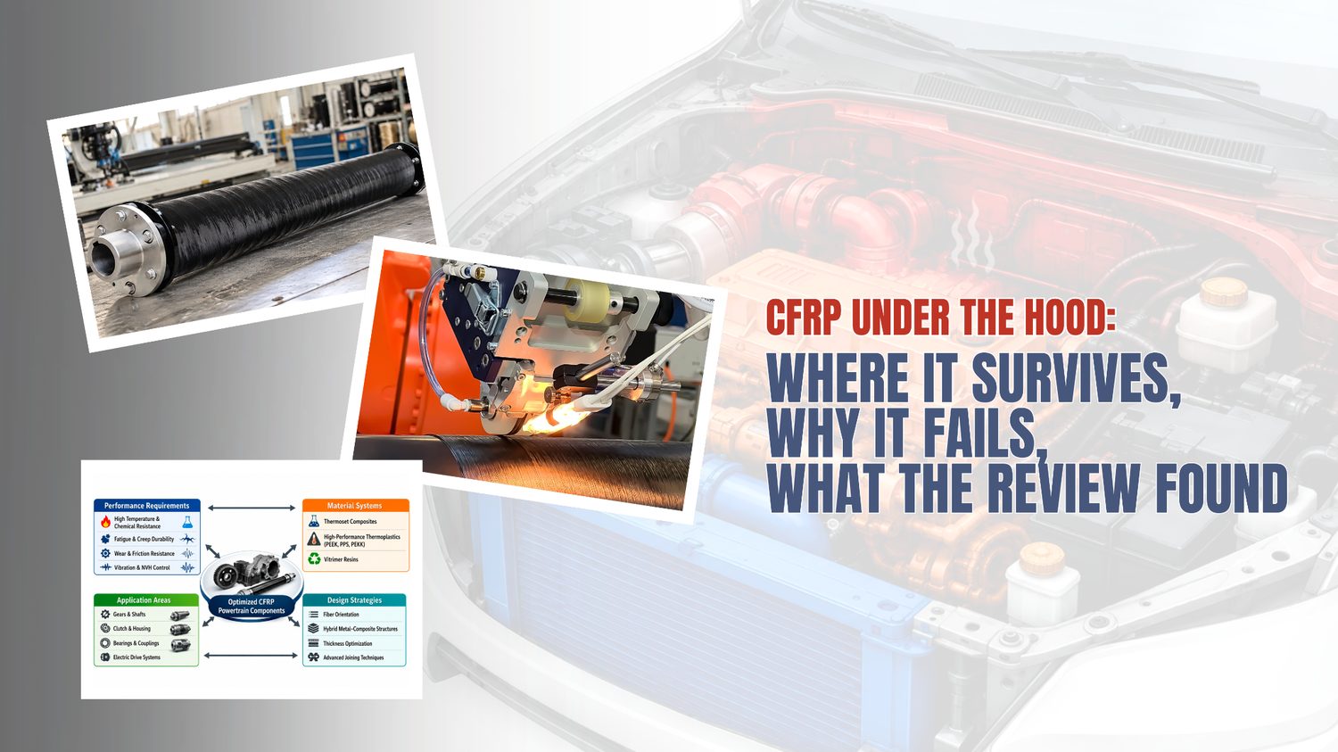
Carbon fibre keeps proving itself in car bodies, chassis, and interiors. Under the hood is a different story. The powertrain is one of the harshest neighbourhoods a structural material can be asked to live in, and until recently the engineering literature treated it in fragments: a fatigue study here, a wear test there, a single housing analysed in isolation. What has been missing is a single reference that connects the operating environment to the material decision across every component category.
A July 2026 open-access review in Polymers (MDPI), authored by Jozef Jaroslav Fekiač, Lucia Kakošová, Michal Krbata, Marcel Kohutiar, Alena Breznická, Pavol Mikuš, Maroš Eckert, and Róbert Janík of Alexander Dubček University of Trenčín, sets out to close that gap. The authors state that a systematic framework tying performance requirements, material selection, structural design, and application-specific powertrain conditions together has been lacking, with most prior work focused on isolated aspects rather than the broader interrelationships. Their review builds that framework.
This post walks through what the review establishes, keeps the authors' findings clearly separated from our own commentary, and looks at what the manufacturing conclusions mean for teams building composite powertrain parts.
A note on sourcing. Everything attributed to “the paper,” “the authors,” or “the review” comes from Fekiač et al. (2026), cited in full at the end. Sections labelled “Our perspective” are Addcomposites' own editorial commentary and are not claims made by, or endorsed by, the paper's authors.
The Problem the Review Is Actually Solving
The core difficulty, as the paper frames it, is that a powertrain component never faces one load at a time. Under the hood, heat, fluids, vibration, sustained load, and sliding contact never arrive on their own schedule. The authors' central point is that these stressors compound one another rather than adding up in a way any single-mechanism model can capture.
That matters because carbon fibre composites behave nothing like the metals they would replace. A steel part usually has one clear route to failure and behaves predictably from cold start to full heat. Composites, the authors point out, are strongly directional in their properties and break down through several coupled processes in the microstructure at the same time. So the question is never simply “is this material strong enough” but “does this material stay stable under everything happening simultaneously, for the whole service life.”
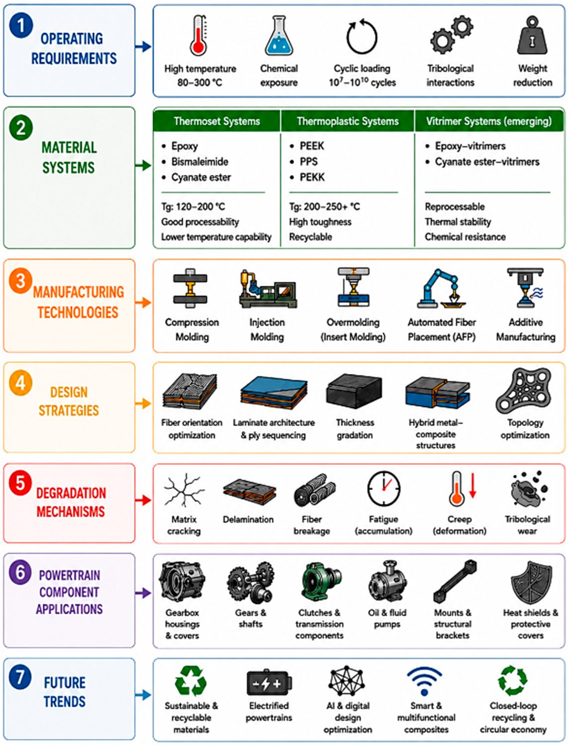
The review's master framework: seven stacked layers —
operating requirements, material systems, manufacturing
technologies, design strategies, degradation mechanisms,
powertrain applications, and future trends — showing how
each CFRP design decision feeds the next rather than standing
alone.
Figure 2 from: Jozef Jaroslav Fekiač, Lucia Kakošová, Michal
Krbata, Marcel Kohutiar, Alena Breznická, Pavol Mikuš, Maroš
Eckert, Róbert Janík. “Carbon Fibre-Reinforced Polymer
Composites for Automotive Powertrain Components: A Comprehensive
Review of Material Systems, Performance Requirements, and
Functional Design Strategies.”
Polymers 2026, 18, 1762.
doi.org/10.3390/polym18141762
— © 2026 by the authors. Licensed under CC BY 4.0 (creativecommons.org/licenses/by/4.0/).
The review's answer to that question is organised around a temperature-zone map, and everything else hangs off it.
The Three Temperature Zones
The paper divides the engine compartment into three thermal zones and assigns typical operating ranges to each. This is the backbone of the whole framework, because the glass transition temperature (Tg) of the polymer matrix has to sit a safe margin above the maximum temperature the component will see. The authors note that engineering practice generally wants roughly 30 to 50 °C of headroom above the peak operating temperature.
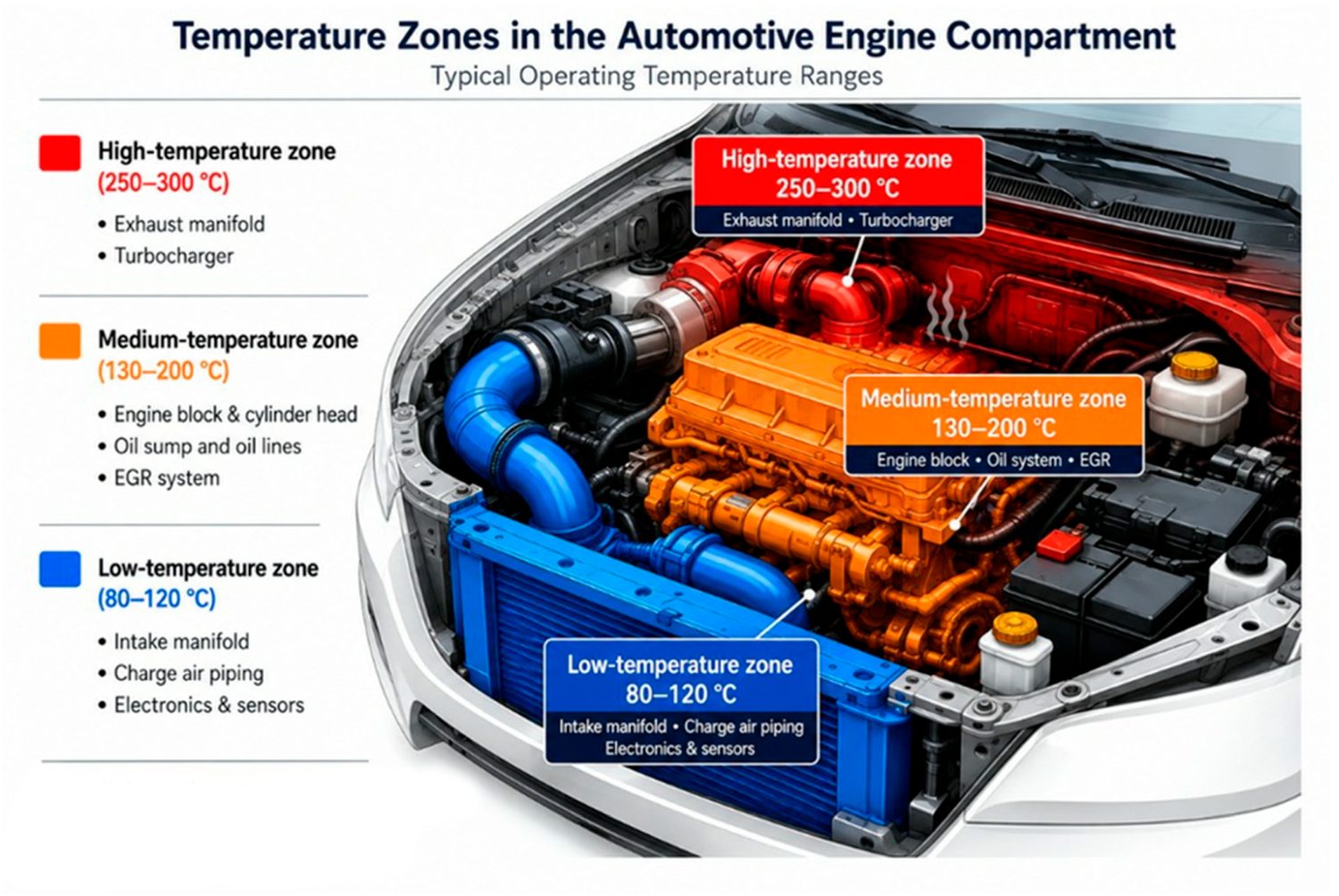
Cutaway of the engine compartment split into three thermal zones
— low (80–120 °C), medium (130–200
°C), and high (250–300 °C) — with typical
components mapped to each, showing why matrix choice is
dictated by where a part sits under the hood.
Figure 3 from: Jozef Jaroslav Fekiač, Lucia Kakošová, Michal
Krbata, Marcel Kohutiar, Alena Breznická, Pavol Mikuš, Maroš
Eckert, Róbert Janík. “Carbon Fibre-Reinforced Polymer
Composites for Automotive Powertrain Components: A Comprehensive
Review of Material Systems, Performance Requirements, and
Functional Design Strategies.”
Polymers 2026, 18, 1762.
doi.org/10.3390/polym18141762
— © 2026 by the authors. Licensed under CC BY 4.0 (creativecommons.org/licenses/by/4.0/).
Two caveats on the zone numbers are worth flagging. The Zone 2 band shown above (130–200 °C) is the figure's label; the paper's text puts the long-term range at 130–180 °C with peaks up to 200 °C, so treat 200 °C as a short-term ceiling rather than a continuous rating. And in Zone 3, the mapping is tighter than it looks: the same review's material table caps CF/PEEK at roughly 250 °C and CF/BMI at roughly 270 °C, so neither actually reaches the top of the 250–300 °C band. The hottest exhaust- and turbocharger-adjacent spots push against the limits of every matrix the paper lists, a tension visible in its own tables.
One nuance the authors are careful to add: for semicrystalline thermoplastics such as PEEK, PPS, and PEKK, Tg alone is misleading. Because their crystalline regions keep carrying load after the amorphous phase softens, these materials can run meaningfully above their Tg. That is precisely why PPS, with a Tg of only around 85 to 100 °C, still holds structural integrity close to its melting point near 280 °C.
The Material Menu, Ranked Against the Zones
Once the zones are set, the review assembles a direct comparison of the candidate matrix systems. The chart below reorganises the property data the authors present in their material-system comparison. The values are the paper's; the layout is ours.
Fekiač et al., Polymers 2026 · material-system comparison
Matrix Systems Ranked by Max Service Temperature
Indicative ranges pulled from many studies, not one shared test protocol — read as guidance, not fixed material constants.
Bars show max continuous service temperature, scaled to 300°C. Source: material-system comparison in Fekiač et al., Polymers 2026, 18, 1762.
With that caveat in place, a clear hierarchy emerges from the authors' analysis:
- CF/PEEK is positioned as the benchmark high-temperature thermoplastic. According to the review, it keeps roughly 70 to 80% of its mechanical properties at elevated temperature (the authors cite around 150 °C), and stays intact above its Tg thanks to its stable crystalline phase.
- CF/PPS is framed as the economically sensible compromise for the medium zone, pairing strong chemical resistance and low fluid uptake with lower cost and easier processing than PEEK. (The 700–900 MPa figure reflects short-fibre and injection-moulded grades; the paper notes continuous-fibre CF/PPS laminates can reach roughly 1200 MPa.)
- CF/PEKK is presented as an emerging option whose wider processing window and slower crystallisation make it easier to consolidate cleanly, which the authors tie specifically to advanced manufacturing routes. (One caveat: the review is internally inconsistent on CF/PEKK strength, with its comparison tables listing 900–1300 MPa and its text citing 1300–1500 MPa; the table value is used above.)
- CF/BMI covers the hottest zone where thermal resistance outweighs its well-known brittleness.
- CF/epoxy remains the reference and the low-cost default for the coolest zone.
- CF/vitrimer is treated as genuinely promising but not yet validated for powertrain duty, a point the authors return to repeatedly.
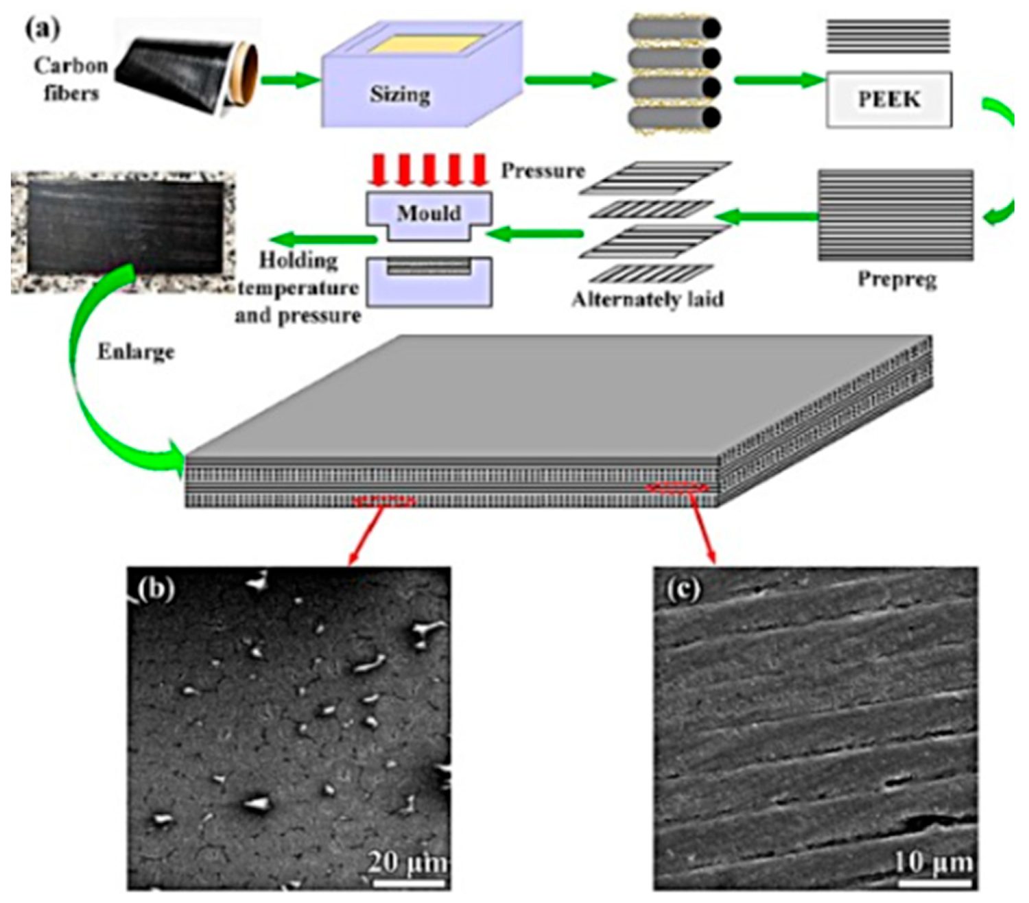
How CF/PEEK is built: the process flows from carbon fibre sizing
and prepreg preparation through alternately stacked plies into
compression moulding under heat and pressure, with SEM panels of
the consolidated laminate showing the tightly packed, aligned
fibres that give the benchmark its low-void performance.
Figure 9 from: Jozef Jaroslav Fekiač, Lucia Kakošová, Michal
Krbata, Marcel Kohutiar, Alena Breznická, Pavol Mikuš, Maroš
Eckert, Róbert Janík. “Carbon Fibre-Reinforced Polymer
Composites for Automotive Powertrain Components: A Comprehensive
Review of Material Systems, Performance Requirements, and
Functional Design Strategies.”
Polymers 2026, 18, 1762.
doi.org/10.3390/polym18141762
— © 2026 by the authors. Licensed under CC BY 4.0 (creativecommons.org/licenses/by/4.0/).
What Actually Breaks, and How Fast
The review's degradation chapter is where the powertrain environment shows its teeth. The authors describe fatigue in CFRP as a staged cascade rather than a sudden event, and they stress that these composites have no clean fatigue limit of the kind engineers rely on with steel.
Fekiač et al., Polymers 2026 · fatigue damage cascade in CFRP
How a CFRP Powertrain Part Actually Fails
Five coupled stages, not a single clean fracture — stiffness typically falls ~10–20% before final failure, and there is no clearly defined fatigue limit, unlike metals.
Two quantified findings from the review stand out for anyone scoping rotating or thermally exposed parts.
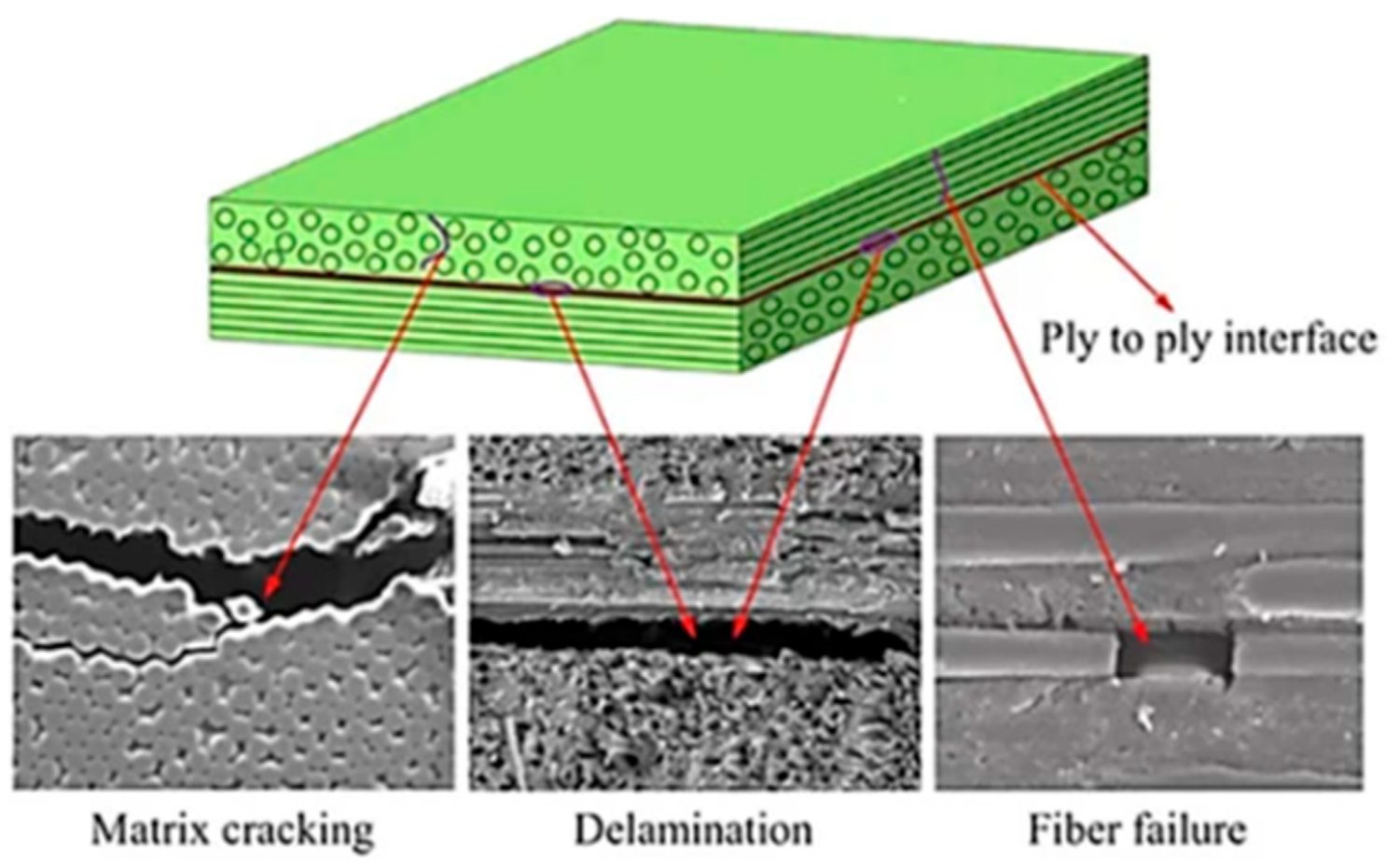
What CFRP failure actually looks like: SEM images of the three
core damage modes — matrix cracking, interlaminar
delamination, and fibre fracture — traced back to the
ply-to-ply interface where the cascade begins.
Figure 5 from: Jozef Jaroslav Fekiač, Lucia Kakošová, Michal
Krbata, Marcel Kohutiar, Alena Breznická, Pavol Mikuš, Maroš
Eckert, Róbert Janík. “Carbon Fibre-Reinforced Polymer
Composites for Automotive Powertrain Components: A Comprehensive
Review of Material Systems, Performance Requirements, and
Functional Design Strategies.”
Polymers 2026, 18, 1762.
doi.org/10.3390/polym18141762
— © 2026 by the authors. Licensed under CC BY 4.0 (creativecommons.org/licenses/by/4.0/).
First, temperature accelerates fatigue sharply. The authors report that a 10 °C rise can shorten fatigue life by roughly 15 to 25%, driven by softening matrix and faster interface degradation.
Second, and more dramatically, creep and fatigue gang up. When time-dependent matrix deformation runs alongside cyclic loading, the paper reports that component lifetime can drop by about 40 to 60% compared with fatigue acting alone, with the worst effects in thermally exposed joints and stress-concentration zones.
Fekiač et al., Polymers 2026 · combined thermomechanical loading
Component Lifetime: Fatigue Alone vs. Creep + Fatigue Combined
A range, not a point estimate — worst effects fall on thermally exposed joints and stress-concentration zones.
Alongside fatigue and creep, the review catalogues delamination and tribological wear. On the wear side, the authors report specific wear rates for CFRP gears in the range of 10−6 to 10−5 mm³/(N·m) at contact stresses between roughly 60 and 150 MPa, and they flag a mechanism unique to composites: once carbon fibres are exposed at a sliding surface, the fractured fibre fragments themselves turn into abrasive third bodies that chew up the counterface, an effect the paper notes is especially severe against soft aluminium alloys.
The Component-by-Component Map
The most useful single artefact in the review, in our view, is its functional classification. Rather than sorting by vehicle type or material, the authors sort powertrain parts by dominant mechanical function, then attach the recommended matrix systems and the main engineering limitation to each.
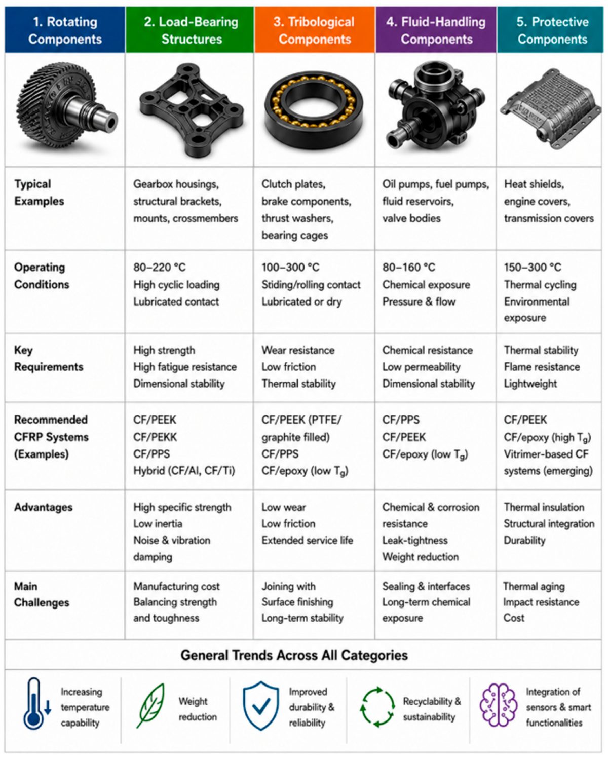
The review's five-way classification of CFRP powertrain
applications — rotating, load-bearing, tribological,
fluid-handling, and protective components — each column
pairing typical parts and operating conditions with recommended
material systems, advantages, and open challenges.
Figure 12 from: Jozef Jaroslav Fekiač, Lucia Kakošová, Michal
Krbata, Marcel Kohutiar, Alena Breznická, Pavol Mikuš, Maroš
Eckert, Róbert Janík. “Carbon Fibre-Reinforced Polymer
Composites for Automotive Powertrain Components: A Comprehensive
Review of Material Systems, Performance Requirements, and
Functional Design Strategies.”
Polymers 2026, 18, 1762.
doi.org/10.3390/polym18141762
— © 2026 by the authors. Licensed under CC BY 4.0 (creativecommons.org/licenses/by/4.0/).
For the three components named in this article's headline, the review's specifics are worth spelling out:
- Drive shafts are governed by torsion. In the authors' account, ±45° plies do the torsional work, and 0° and 90° layers are added to stiffen the shaft in bending and push its critical speed higher. They cite a Formula-class shaft study using a [90/0/-45/+45]s layup; in the authors' words, this sequence “provides the best combination of torsional stiffness, bending natural frequency, and low weight.” A recurring design rule in the paper: keep the first natural frequency at least 20 to 30% above the maximum operating speed to avoid resonance.
- Gears are harder. Because the mesh pushes perpendicular to the tooth face, a composite gear has to survive root bending and surface contact pressure at the same time. The authors describe hybrid steel-rim-on-CFRP-hub constructions as the practical route: the design trims 30 to 60% of gear mass while leaving the hard-wearing steel exactly where the teeth engage.
- Connecting rods see alternating tension and compression with stress amplitudes the paper puts at about 300 to 600 MPa, accumulating to cycle counts on the order of 108 to 109 over an engine's life. The critical regions, according to the authors, are the bolt and pin holes, where the holes interrupt fibre continuity and concentrate stress.
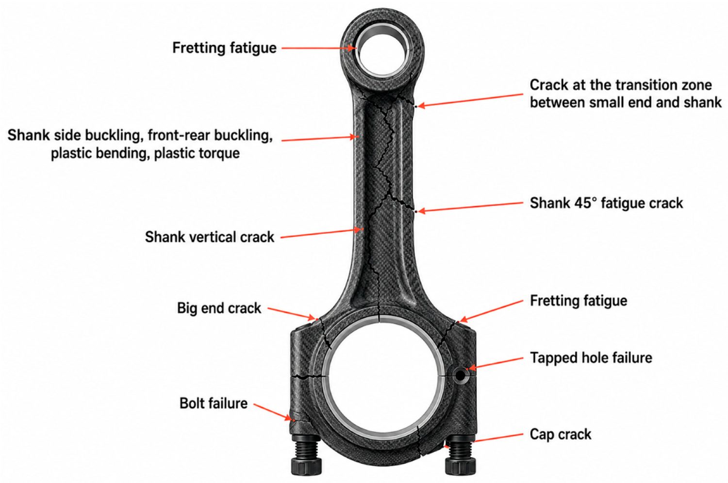
A CFRP connecting rod annotated with its characteristic failure
sites under cyclic loading — fretting fatigue at the ends,
shank and big-end cracks, tapped-hole and bolt failure —
highlighting the bolt and pin holes as the critical
stress-concentration regions.
Figure 13 from: Jozef Jaroslav Fekiač, Lucia Kakošová, Michal
Krbata, Marcel Kohutiar, Alena Breznická, Pavol Mikuš, Maroš
Eckert, Róbert Janík. “Carbon Fibre-Reinforced Polymer
Composites for Automotive Powertrain Components: A Comprehensive
Review of Material Systems, Performance Requirements, and
Functional Design Strategies.”
Polymers 2026, 18, 1762.
doi.org/10.3390/polym18141762
— © 2026 by the authors. Licensed under CC BY 4.0 (creativecommons.org/licenses/by/4.0/).
Why Manufacturing Quietly Decides Survival
Here is the part of the review that we think deserves more attention than it usually gets. The authors are clear that picking the right matrix gets you only part of the way. How a part is made drives how much porosity it carries, how well the fibres line up, how strong the fibre-to-resin bond is, and how close it holds tolerance, and those factors in turn set the fatigue and durability behaviour the earlier chapters spent so long analysing.
The paper's process comparison makes the trade-offs plain.
Fekiač et al., Polymers 2026 · manufacturing route comparison
Void Content by Manufacturing Route
Shorter bar = lower void content. AFP holds the lowest void content in the table — the exact place CF/PEEK's sub-1% requirement needs to land.
The authors tie this back to the high-performance thermoplastics directly. They note that CF/PEEK requires very low void content, below 1%, to perform, and they name automated fibre placement alongside prepreg compression moulding as the technologies able to hit that target. Separately, they highlight that PEKK's broader processing window and slower crystallisation make it particularly well suited to AFP and other automated routes where precise thermal control across the deposition cycle is what governs final part quality.
Our perspective
This is the practical crux for anyone moving from a material spec to a real part. The review's own data puts AFP at the bottom of the void-content column, the exact place a CF/PEEK or CF/PEKK drive shaft needs to be. That aligns closely with why AFP exists as a process: laying continuous tape down a defined path, with controlled heat and consolidation, is how you reach the very low void content the paper ties to AFP and prepreg compression moulding. In practice, in-situ thermoplastic placement of PEEK and PEKK lands around 2% porosity in our own published figures, with the lowest voids reached when placement is paired with a consolidation step.
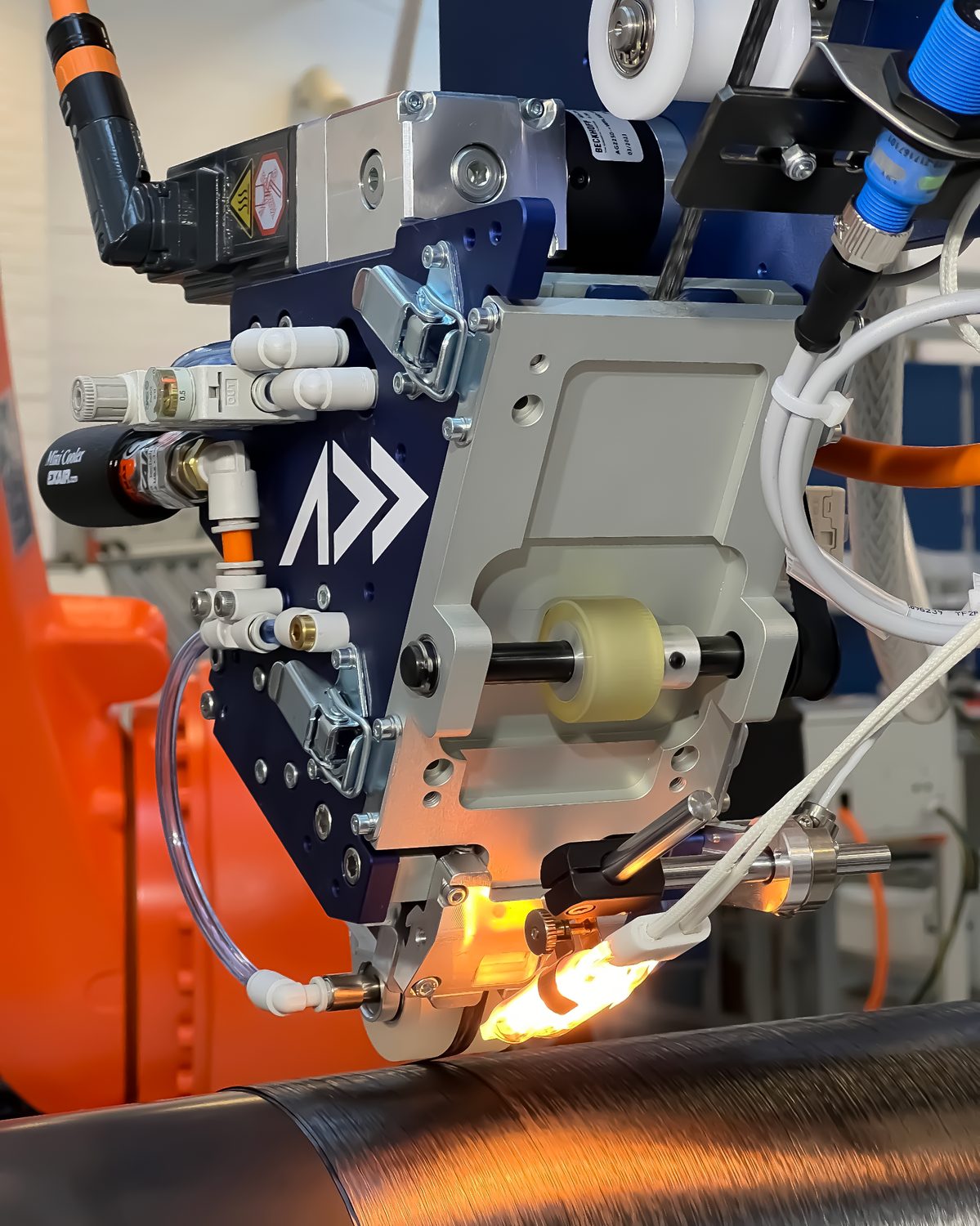
Addcomposites AFP-XS head depositing continuous carbon fibre tow onto a rotating mandrel, with the heat source and compaction roller consolidating the tape in situ to achieve low void content.
For teams scoping powertrain parts, our reading is that AFP is the natural entry point for the rotating and structural components the review flags as continuous-fibre territory. An AFP-XS cell is a sensible first step for getting hands on thermoplastic layup, drive-shaft-scale tubes, and structural sections without committing to a large installation. Where the part grows — longer shafts, larger housings, bigger consolidated sections — the four-tow AFP-X head extends the same process to larger components and higher-volume production. And because the review keeps returning to fibre orientation and stacking sequence as the decisive design levers, path-planning software such as AddPath is where much of that ±45° torsion optimisation and ply sequencing actually gets translated into a manufacturable layup.
None of this is a claim the paper's authors endorse any product or vendor. It is our interpretation of how their manufacturing conclusions map onto AFP as a process.
Design Strategy: The Levers the Review Keeps Pulling
Across its design chapter, the review returns to four strategies as the toolkit for making CFRP powertrain parts work: fibre orientation, thickness gradation, ribbing, and hybrid metal-composite structures. A few numbers the authors attach to these:
- Properly optimised laminates can cut load-bearing component weight by roughly 60 to 80% versus steel.
- Thickness gradation, concentrating material where stress is highest, is credited with about 15 to 25% weight reduction while holding fatigue safety.
- Thin plies below 100 µm are reported to hold back the start of cracks between layers and to stretch out fatigue life.
- Hybrid CFRP-metal joints, particularly combined adhesive-and-mechanical joints, are presented as the most realistic path to industrial adoption, though the authors flag galvanic corrosion between carbon fibre and metal as a real hazard needing insulation and surface treatment.
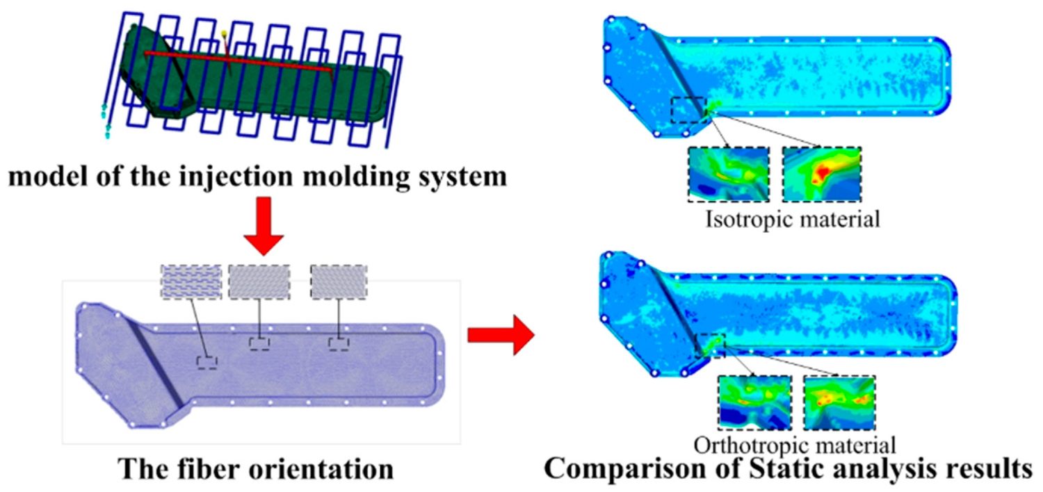
Isotropic versus orthotropic modelling of a CFRP housing
component: the side-by-side stress and deformation plots show
how accounting for fibre orientation changes the predicted
response, underlining why composite parts cannot be analysed as
if they behaved like metal.
Figure 15 from: Jozef Jaroslav Fekiač, Lucia Kakošová, Michal
Krbata, Marcel Kohutiar, Alena Breznická, Pavol Mikuš, Maroš
Eckert, Róbert Janík. “Carbon Fibre-Reinforced Polymer
Composites for Automotive Powertrain Components: A Comprehensive
Review of Material Systems, Performance Requirements, and
Functional Design Strategies.”
Polymers 2026, 18, 1762.
doi.org/10.3390/polym18141762
— © 2026 by the authors. Licensed under CC BY 4.0 (creativecommons.org/licenses/by/4.0/).
What ties the design chapter to the manufacturing chapter is fibre orientation. The paper stresses that the layup a solver calls optimal often runs into real production limits: how tightly tape can steer, how sharply it can turn, where plies can be dropped, and whether the stack consolidates cleanly. That is a manufacturing-aware design problem, and it is exactly the space where automated deposition and its associated path planning earn their place.
Where the Review Lands, and Where It Stays Cautious
The authors' overall conclusion is deliberately unromantic. In their words, “no universal CFRP system exists for all powertrain components.” Picking a material instead becomes a balancing act, weighed differently for each part: how well it takes heat, how it holds up under cyclic and sliding loads, whether it can be built at volume and recycled at end of life, and what it costs, all judged against that component's specific duty cycle.
They are especially measured about vitrimers. Despite the recyclability and repairability upside, the review repeatedly notes that long-term behaviour under simultaneous heat, fluid, and cyclic-load exposure has not yet been validated for the powertrain, and it explicitly warns against using vitrimer CFRP for highly loaded rotating parts until that validation exists. It is a refreshingly honest note in a field that often oversells its newest chemistry.
Our perspective
The value of this review for our industry is that it turns “could CFRP work here” into a structured, zone-by-zone, component-by-component question with the manufacturing constraints written in from the start. For anyone deciding which powertrain parts are realistic composite targets today, it is a strong, current, single-source reference, and its manufacturing conclusions point squarely at continuous-fibre, low-void processes. Again, this is our analysis of the paper's implications, not a position taken by its authors.
For teams deciding which powertrain parts are realistic composite targets today, that manufacturing conclusion is where the conversation usually starts with us: AFP-XS and AFP-X are built for exactly the low-void, continuous-fibre layup the review ties to CF/PEEK and CF/PEKK performance, and AddPath handles the ±45°/0°/90° stacking-sequence work the paper's design chapter keeps coming back to. If you're scoping a drive shaft, gear hub, or connecting rod for composite conversion, talk to us →
Talk to the Addcomposites team about moving a powertrain part from a material spec to a low-void, production-ready layup →
Get in Touch with Addcomposites
References
- Jozef Jaroslav Fekiač, Lucia Kakošová, Michal Krbata, Marcel Kohutiar, Alena Breznická, Pavol Mikuš, Maroš Eckert, Róbert Janík. “Carbon Fibre-Reinforced Polymer Composites for Automotive Powertrain Components: A Comprehensive Review of Material Systems, Performance Requirements, and Functional Design Strategies.” Polymers 2026, 18, 1762. doi.org/10.3390/polym18141762. Open access, published 18 July 2026, under the Creative Commons Attribution (CC BY 4.0) license (creativecommons.org/licenses/by/4.0/).
