Recycled Carbon Fibre Just Passed a Scaled Wing Spar Test, Not Just a Coupon Test
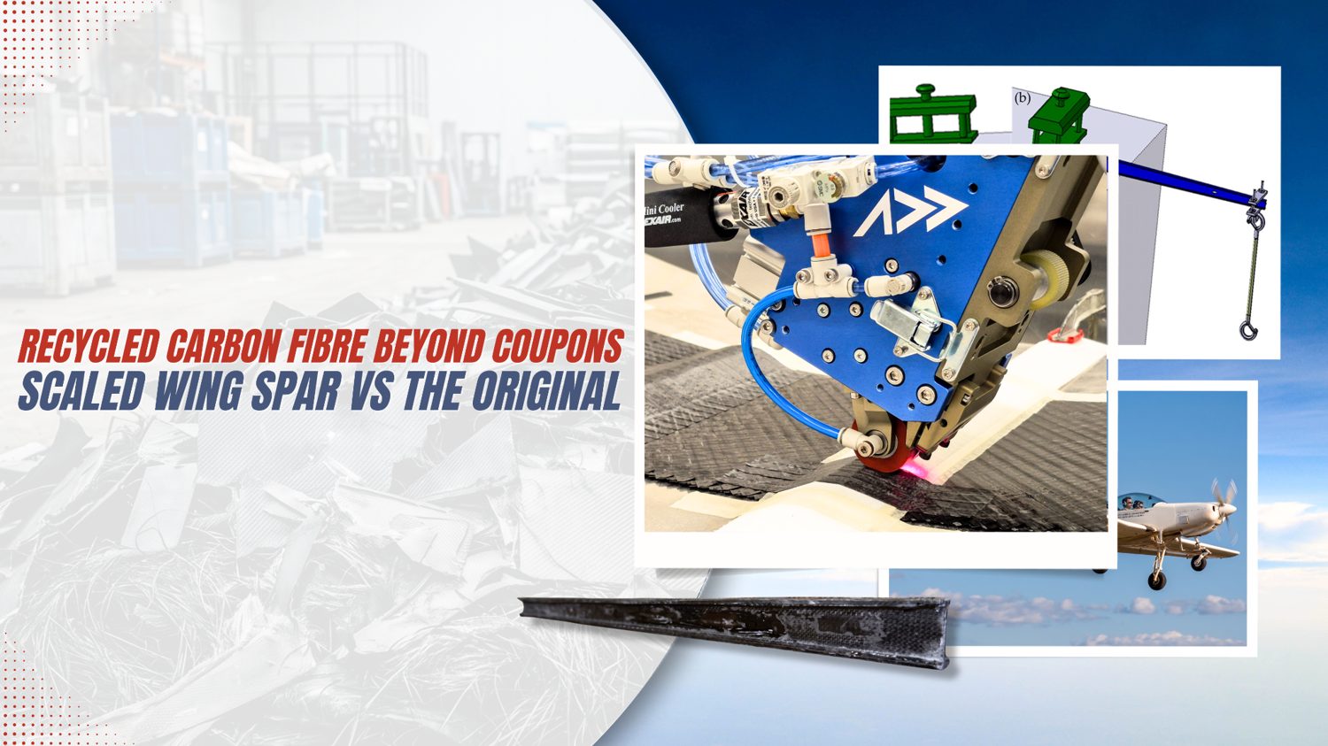
Most recycled carbon fibre studies stop at the coupon. A July 2025 open-access paper takes the harder path — it builds a scaled aircraft wing spar out of pyrolysis-recovered fibre and benchmarks it against the original composite spar under representative lift and drag loading.
You pyrolyse some end-of-life prepreg, pull clean fibre out the other side, lay it into a dog-bone specimen, tensile-test it, and report a number. That number is useful, but it is also where the conversation with an aerospace structural engineer usually stalls. A coupon tells you what a material can do in a controlled strip. It does not tell you whether a real load-bearing part built from that material will hold up when the loads are shaped like flight.
A July 2025 open-access paper in the Journal of Composites Science (MDPI) takes the harder path. The authors built a scaled-down aircraft wing spar out of recycled carbon fibre, based on the geometry of a real airplane, and put it up against a conventional composite spar under representative lift and drag loading, using a validated finite-element model plus physical testing of the recycled part. In other words, they scaled recycled fibre up from “material property” to “structural component” and then asked the question that actually matters for structural qualification: does the part behave like the original?
Below we walk through what the paper did, what it found, and where the honest limits are. At the end, clearly fenced as our own commentary, we offer the Addcomposites perspective on what this means for anyone weighing recycled feedstock for real structures.
Why a component-level test is the interesting part
According to the paper, the broader problem it addresses is that carbon fibre composites deliver excellent stiffness-to-weight and strength-to-weight, but their growth in aircraft has created a waste stream that is hard to justify environmentally. The authors point to recycling as the route out of that bind, provided the recovered fibre keeps enough of its mechanical performance to be worth reusing.
That “provided” is the whole game. This is context worth adding from outside the paper: across the industry, aerospace-grade recycled fibre is often diverted into lower-value uses like interior panels and semi-structural parts, precisely because structural reuse standards are strict and the data needed to clear them at the part level is thin. Recent market coverage (Global Market Insights' 2025 aerospace-composite-recycling analysis for the segment figures, and recycled-fibre supplier Advanced Composites Engineering for the emissions and cost figures) puts the thermal (pyrolysis) segment of aerospace composite recycling at roughly USD 39.9 million in 2024, with end-of-life aircraft components generating around USD 59.9 million, and estimates that recycled carbon fibre can cut CO2 emissions by up to 80% and material cost by 20–40% versus virgin fibre. The appetite is real; the structural evidence is what lags.
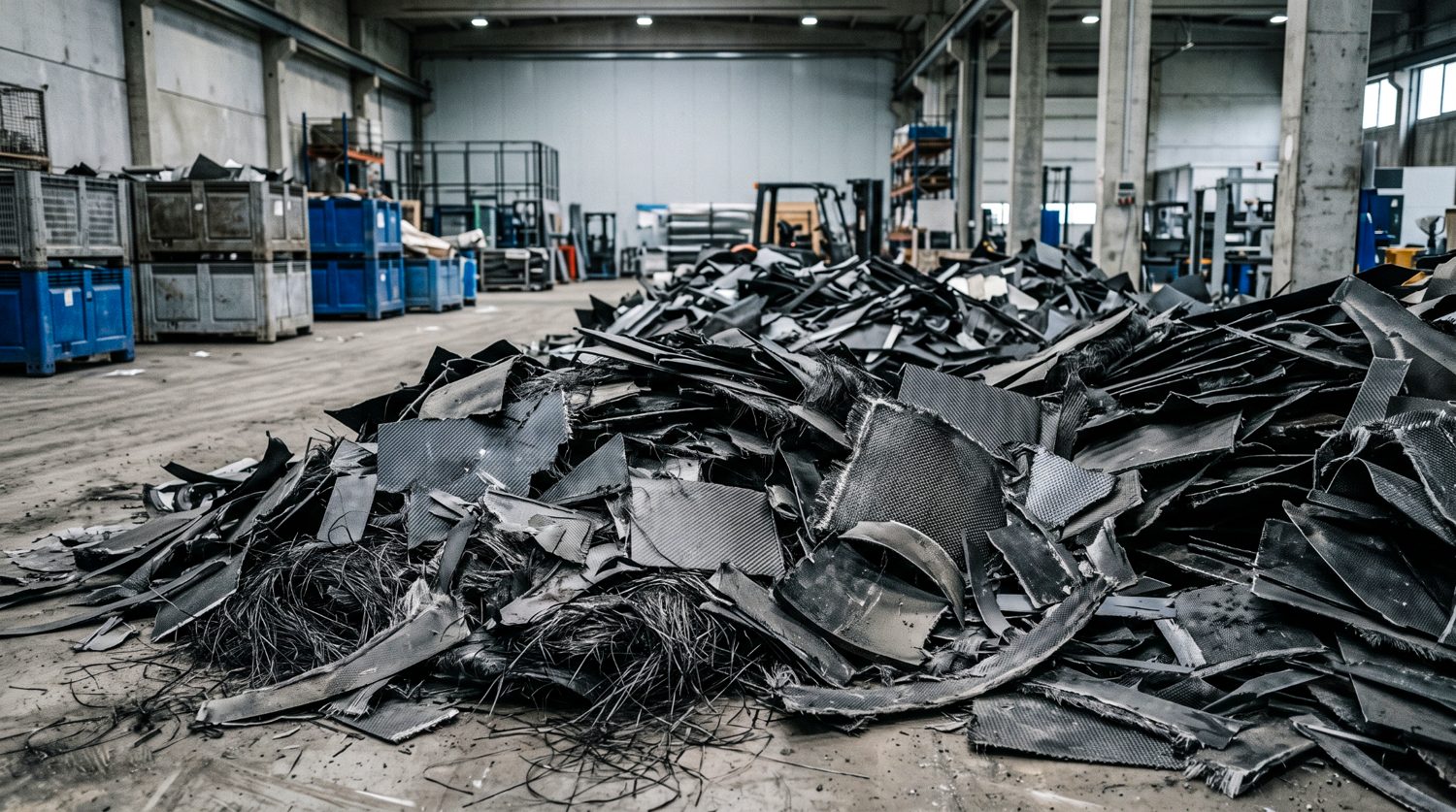
Industrial carbon fibre composite waste awaiting recycling. The volume of end-of-life CFRP scrap continues to outpace pathways for high-value structural reuse. Image for illustrative purposes only.
That is why a wing-spar-level result reads differently from yet another coupon comparison. A spar is a primary load path, so validating one — even at reduced scale and even at a laboratory technology-readiness level — is a data point you can actually take into a structures conversation.
The aircraft and the part

Aeromot AMT-600 Guri, the single-engine composite trainer whose wing geometry the study is scaled from. Illustrative image.
The paper builds everything around the AMT-600 GURI, a Brazilian-built single-engine trainer with a low cantilever wing, produced by Aeromot. The authors describe it as a two-seat aircraft used for early pilot training, flying a NACA 64(3)-618 wing section on a mostly composite airframe. From the manufacturer's manual, they pull the flight and geometry data needed to set up the loads: a maximum take-off weight around 900 kgf, a span of 10.5 m, a wing area near 13.8 m², and root and tip chords of roughly 1.795 m and 0.997 m respectively.
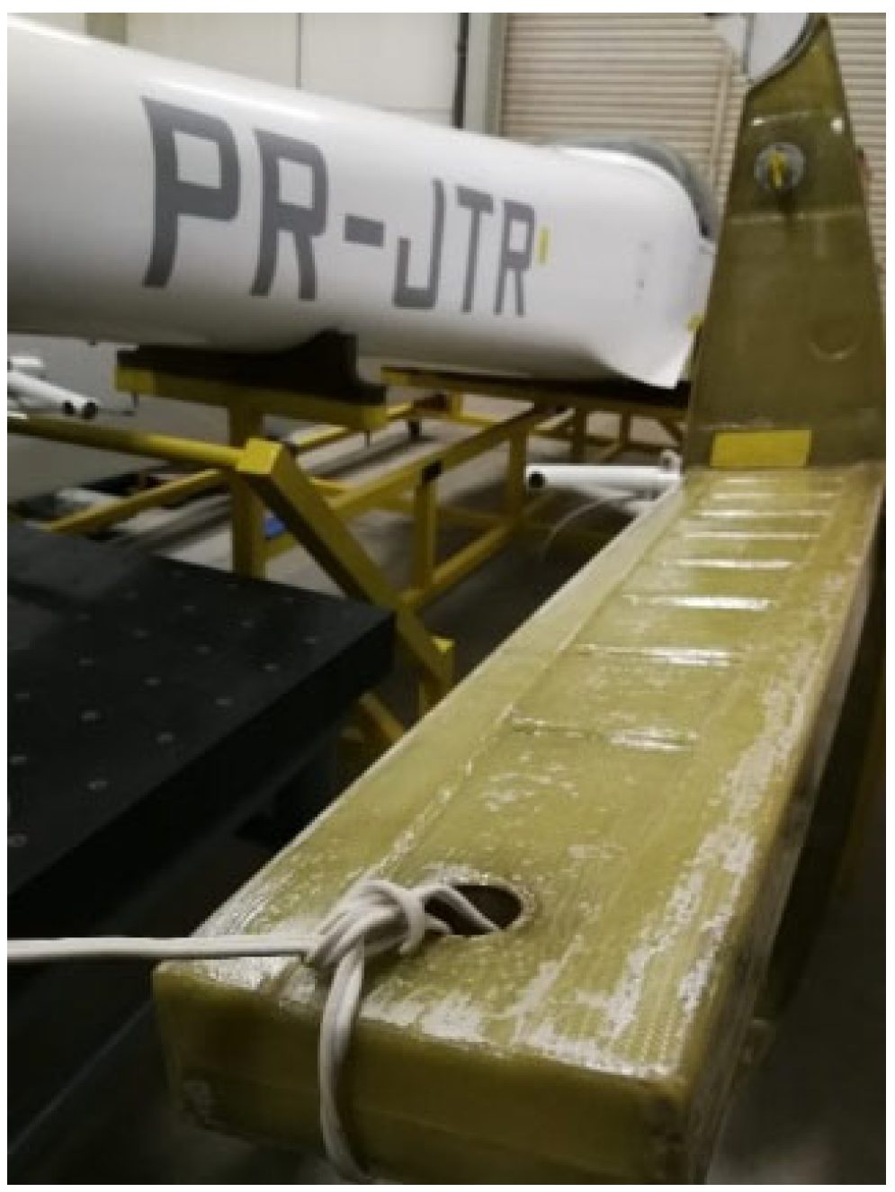
The AMT-600 GURI composite wing spar, shown removed from the wing.
This is the primary bending member the study set out to reproduce
in recycled carbon fibre.
Figure 2 from: Bouman, N.; Marques, S.S.L.; Sebbe, N.P.V.;
Gerritse, A.; Bernardi, H.H.; Menezes, W.M.M.; da Silva, F.J.G.;
Matsushima, J.T.; Giovanetti, L.; Sales-Contini, R.d.C.M.
“Advancing Sustainability in Aerospace: Evaluating the
Performance of Recycled Carbon Fibre Composites in Aircraft Wing
Spar Design.” Journal of Composites Science 2025, 9,
384.
doi.org/10.3390/jcs9080384
— © 2025 by the authors. Licensed under CC BY 4.0 (creativecommons.org/licenses/by/4.0/).
The wing spar is the beam that carries bending in the wing. Reproducing the spar's behaviour is about as close as a scaled test can get to reproducing the wing's structural fate, since it is the member most responsible for surviving flight loads.
Step one: figure out the loads without a wind tunnel run
Rather than physically test the full aircraft, the authors used a wind tunnel simulation of the GURI wing to estimate the pressure field, then fed that into a finite-element model built in Altair HyperWorks (HyperMesh for pre-processing, OptiStruct as the solver). Because the simulated pressure came out roughly even across the wing, they were able to collapse the loading into a single value: about 5500 Pa pressing normal to the wing's outer surface, applied under a defined flight condition (about 298 K, 101,325 Pa, air density 1.184 kg/m³, airspeed 69.44 m/s, 12° angle of attack).
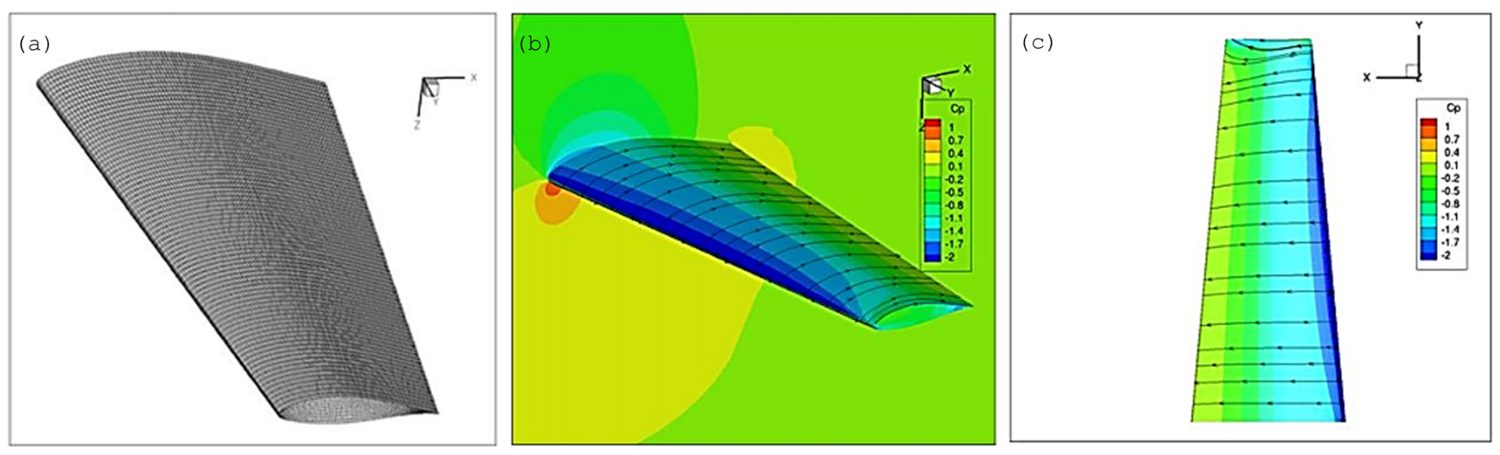
The finite-element mesh of the GURI wing (left) and the simulated
pressure distribution across its surface (centre and top-down
views). The near-uniform pressure field is what let the authors
collapse the aerodynamic load into a single equivalent value.
Figure 1 from Bouman et al., Journal of Composites Science
2025, 9, 384.
doi.org/10.3390/jcs9080384
— © 2025 by the authors. Licensed under CC BY 4.0 (creativecommons.org/licenses/by/4.0/).
The wing was restrained the way a real cantilever behaves, locked solid where it meets the fuselage and left unconstrained out at the tip. The run itself was linear and quasi-static. Engineers reach for that kind of analysis early in a programme precisely because it answers the load-bearing question quickly and cleanly, before more expensive, higher-fidelity work is justified.
The clever bit: validate the model on cheap plastic first
Here is the part of the methodology we found genuinely smart, and it is worth spelling out because it is the reason the recycled-fibre numbers are trustworthy rather than hopeful.
You cannot trust a simulation of a recycled composite spar unless you first trust the simulation method. So before touching recycled fibre, the authors printed the spar and a set of test specimens in ABS plastic using fused-deposition 3D printing, tested those physically, and used the results to tune and confirm the finite-element workflow. Only after the method reproduced the cheap-plastic reality did they apply the same method to the recycled composite. The overall program looks like this.
Method — Bouman et al., 2025
The four-stage validation pipeline
Nothing about the recycled spar is trusted until the modelling method has already reproduced physical reality on a cheap, well-understood material.
Concept + loads
- Wind-tunnel simulation of the GURI wing
- Build the FE model in HyperWorks
Output: pressure field & boundary conditions
ABS model check
- 3D-print the ABS spar + coupons
- Physical tests: tensile, compression, flexural, shear
Output: FE method tuned to match ABS reality (Setup 7 wins)
Recycled spar
- Pyrolyse F593 prepreg → recovered fibre
- Hand layup + vacuum-bag build
- Physically test the recycled spar
Output: measured spar behaviour
Compare
- Recycled spar vs the original composite spar
- Lift + drag, stress + deflection
Conclusion: feasibility at TRL 4
Addcomposites' summary of the workflow reported by the authors.
Because the spar is longer than the print bed, the ABS version had to be printed in three pieces and joined. The authors bonded the pieces using acetone vapour, which softens ABS enough to fuse the surfaces, and then validated that joint with a lap-shear test to ASTM D5868. The paper reports that the acetone-bonded joints actually carried more load than joints printed as one piece: about 2.11 ± 0.03 kN for the acetone bond versus 1.79 ± 0.04 kN for the printed joint. That is a tidy little result on its own, and it cleared the joining method for use in the validation model.
On the ABS coupons, the tuned simulation setup (the authors' “Setup 7,” using R-trias 2D and tetrahedral 3D elements at 0.5 mm) tracked the physical tests closely. For tensile, the measured stress was 31.69 ± 0.45 MPa against a simulated value the paper reports as roughly 31 to 32 MPa (30.91 MPa in the text, 32.34 MPa for Setup 7 in Table 8), a gap of only about 2%. Compression displacement matched to about 2% (15.53 mm measured, 15.29 mm simulated), though compression stress diverged more: against a measured 110.55 MPa, the paper quotes its own simulation inconsistently as both 151.7 MPa and 98.71 MPa. The authors flag that divergence rather than paper over it, and the exercise still did its job: the modelling method mirrored physical displacement closely enough to justify carrying it forward.
Getting the recycled fibre: pyrolysis of F593 prepreg
The recycled reinforcement came from HexPly F593 prepreg, a plain-weave Toray T300/3k carbon fabric in an epoxy matrix. The authors recovered the fibre by pyrolysis, thermally treating the cured prepreg at 500 ± 10 °C for four hours in a high-purity argon atmosphere, following the same procedure established in their earlier work (Sales-Contini et al., 2024). Pyrolysis drives the resin off thermally with oxygen excluded, leaving the reinforcing fibre behind.
The paper is candid that pyrolysis is not free of consequences for the fibre. Citing Fernandez et al., the authors note that pyrolysed F593 loses roughly 10% of its elastic modulus, about 30% of its tensile strength, and around 12% of its fibre diameter, with that thinning tied to an amorphous carbon skin being stripped off during the thermal cycle. This matters: the recycled spar was never going to be a like-for-like clone of virgin material at the fibre level, so the real test is whether careful design at the part level closes that gap.
To model the recovered fabric accurately, the authors characterised it under SEM and measured the geometry of the woven unit cell, treating each tow cross-section as an ellipse. Those measurements fed a Multiscale Designer model of the plain weave.
Table 7 — Bouman et al., 2025
Recycled F593 woven unit cell
SEM-measured plain-weave geometry, with each tow cross-section treated as an ellipse. The authors note relatively small tows with relatively wide spacing, consistent with matrix and sizing loss during pyrolysis.
Values reproduced as data from Table 7 of Bouman et al., 2025; the layout is our own.
Building and testing the recycled spar
The recycled spar itself was made by hand layup with vacuum bagging. Each recycled carbon fibre layer was combined with an Araldite LY 5052 / Aradur 5052 epoxy system mixed at 100:38 by weight, at a per-layer thickness of about 0.190 mm, stacked as symmetric laminates. The authors used the simulation to screen fibre orientations and settled on a 45°/−45° layup, chosen to match the fibre direction of the original GURI composite spar.
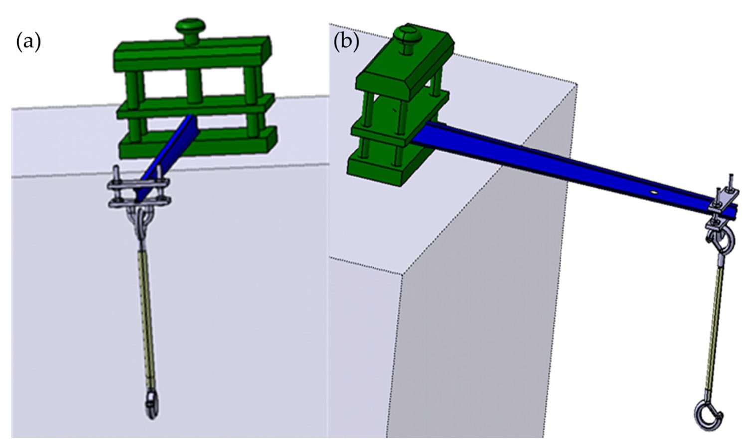
The purpose-built test support, shown in front view (a) and side
view (b). The spar is held in a fixed clamp at one end while load
is applied at the free end, replicating the cantilever
configuration of a real wing.
Figure 5 from Bouman et al., Journal of Composites Science
2025, 9, 384.
doi.org/10.3390/jcs9080384
— © 2025 by the authors. Licensed under CC BY 4.0 (creativecommons.org/licenses/by/4.0/).
Both spars were then loaded in a purpose-built rig. Load was applied by hanging graduated sandbags from a hook-and-rope at the free end, while the opposite end sat in a counterweighted clamp that held it steady. Displacement under lift-direction and drag-direction loading was recorded, and the classic beam relationships (moment of inertia, Euler–Bernoulli deflection, and the corresponding modulus back-calculation) were used to turn those measurements into stress, strain and modulus inputs for the model.
Before trusting the composite spar simulation, the authors again validated the method on recycled composite coupons. Displacement agreement was reasonable: in tension, 2.04 mm simulated against 2.29 mm measured (about a 12% gap); in compression, 14.44 ± 1.45 mm simulated versus 15.53 mm measured (about 8%). The stress comparisons, though, are harder to trust, and this is worth flagging plainly. The paper's tabulated “mechanical test” reference values for the recycled coupons (31.69 MPa in tension, 110.55 MPa in compression) are byte-for-byte identical to its ABS coupon figures, and both sit far below the 1,416 to 1,643 MPa the same paper elsewhere reports as the composite's maximum stress. Those reference numbers appear to have been carried over from the ABS dataset, so we read the recycled-coupon displacement match as the meaningful validation and treat the tabulated stress percentages as unreliable in the source. With displacement confidence established, the authors ran the spar comparison.
The headline result: recycled spar vs original spar
This is the comparison the whole paper is built toward. Using the validated model, the authors put the recycled carbon fibre spar side by side with the original AMT-600 GURI composite spar, under both lift and drag, for maximum displacement and maximum stress.
Two caveats matter before reading the table. First, this is a simulation-to-simulation comparison: the original spar was not rebuilt and physically tested here, so its numbers come from the model, not a bench. Second, in the physical recycled-spar test the loading rig's clamp began to fail before the spar did, so the spar was never driven to its own structural limit; it simply showed no failure at the loads that could be reached.
Table 15 — Bouman et al., 2025
Recycled CFRP spar vs original composite spar
Maximum displacement and maximum stress under lift and drag loading. Bars are scaled within each metric; longer is not “better” — for displacement, shorter means stiffer.
Lift — max displacement
Difference reported: 116.27%Recycled deflects less — the recycled spar is the stiffer performer under lift.
Lift — max stress
Difference reported: 8.95%Recycled runs slightly higher stress at the critical point.
Drag — max displacement
Difference reported: 114.72%Recycled deflects more — here the original spar is the stiffer performer.
Drag — max stress
Difference reported: 36.00%The recycled spar's weak point. The higher drag stress is what the authors identify as making it a little worse than the original in that scenario.
Values reproduced as data from Table 15 of Bouman et al., 2025; the reading annotations are our own.
It is worth being precise about how the authors themselves interpret this, because the framing in the abstract and the framing in the discussion are not identical, and readers should see both. The abstract presents the +8.95% lift stress and +36% drag stress as increases relative to the original spar. The discussion is more measured: it states that the recycled spar performs slightly better than the original under lift, that the original performs better under drag, and that the higher drag stress is ultimately what makes the recycled spar a little worse than the original in that scenario. Taken together, the authors conclude that the recycled spar ends up with characteristics close to the original GURI spar, close enough that they judge the recycled part feasible for the application. In the paper's own words, the recycled spar has “almost equal characteristics to the original composite spar.”
A higher maximum stress under a fixed load is not automatically an “improvement,” since it can equally indicate that the part is working harder at its critical point. The displacement figures are the cleaner read here: the recycled spar is genuinely stiffer under lift and genuinely more flexible under drag. We would encourage anyone citing this study to lead with the displacement comparison and the feasibility conclusion, and to treat the stress percentages as descriptive rather than as evidence that recycled outperforms virgin. The authors flag the same drag-stress caveat themselves.
What the authors claim, and what they explicitly do not
The paper positions this as a Technology Readiness Level 4 result, meaning the design has been proven on physical hardware under controlled lab conditions rather than in service. According to the authors, the study demonstrates that a GURI-style wing spar can in fact be manufactured from pyrolysis-recovered carbon fibre and can reach performance close to the original composite spar, which is the feasibility bar they set out to clear.
Scope — where this study sits
Technology Readiness Levels
The standard 1–9 TRL scale, with the study's own stated result marked.
TRL 4 means the recycled spar was proven on real hardware under controlled laboratory conditions — not tested in flight or in a real operating environment. Read it as “feasible and validated at lab scale,” not “certified for flight.” Fatigue, environmental durability and production economics all sit at higher TRLs the authors leave to future work.
Addcomposites' summary of the standard 1–9 TRL scale, positioning the study's stated TRL 4 result.
Just as important is what they rule out of scope. The authors are explicit that this work covers quasi-static structural behaviour only. Three questions are left open as future work before mass production could be entertained: how the material holds up under fatigue, how it weathers real operating environments, and whether the economics actually close at production volume. That is the correct posture, and it is why the honest one-line summary of this paper is “feasible and validated at lab scale,” not “certified for flight.”
Our perspective: what this means for recycled feedstock in real structures
Everything in this section is Addcomposites' own commentary. It does not originate from the paper, and nothing here should be read as an endorsement of Addcomposites or its products by the study's authors.
For teams weighing recycled carbon fibre for load-bearing parts, the value of this study is less about the specific megapascal figures and more about the shape of the evidence. The authors did the thing that recycled-fibre advocates are usually missing: they carried the material all the way up to a representative primary structure and benchmarked it against the incumbent. That is the kind of data point that moves recycled fibre from a sustainability slide into a structures review.
A few things we would flag from a manufacturing standpoint.
Feedstock format is the real scale-up question
The study used pyrolysis-recovered woven fabric laid up by hand. Hand layup and vacuum bagging are exactly right for a one-off laboratory prototype, and they are what the authors used. They are not how you build parts repeatably at rate. The gap between “we proved the material works in a spar” and “we can produce spars consistently” is a process-control gap, and it is the gap automated fibre placement exists to close, through repeatable layup, controlled compaction, and traceable process data.
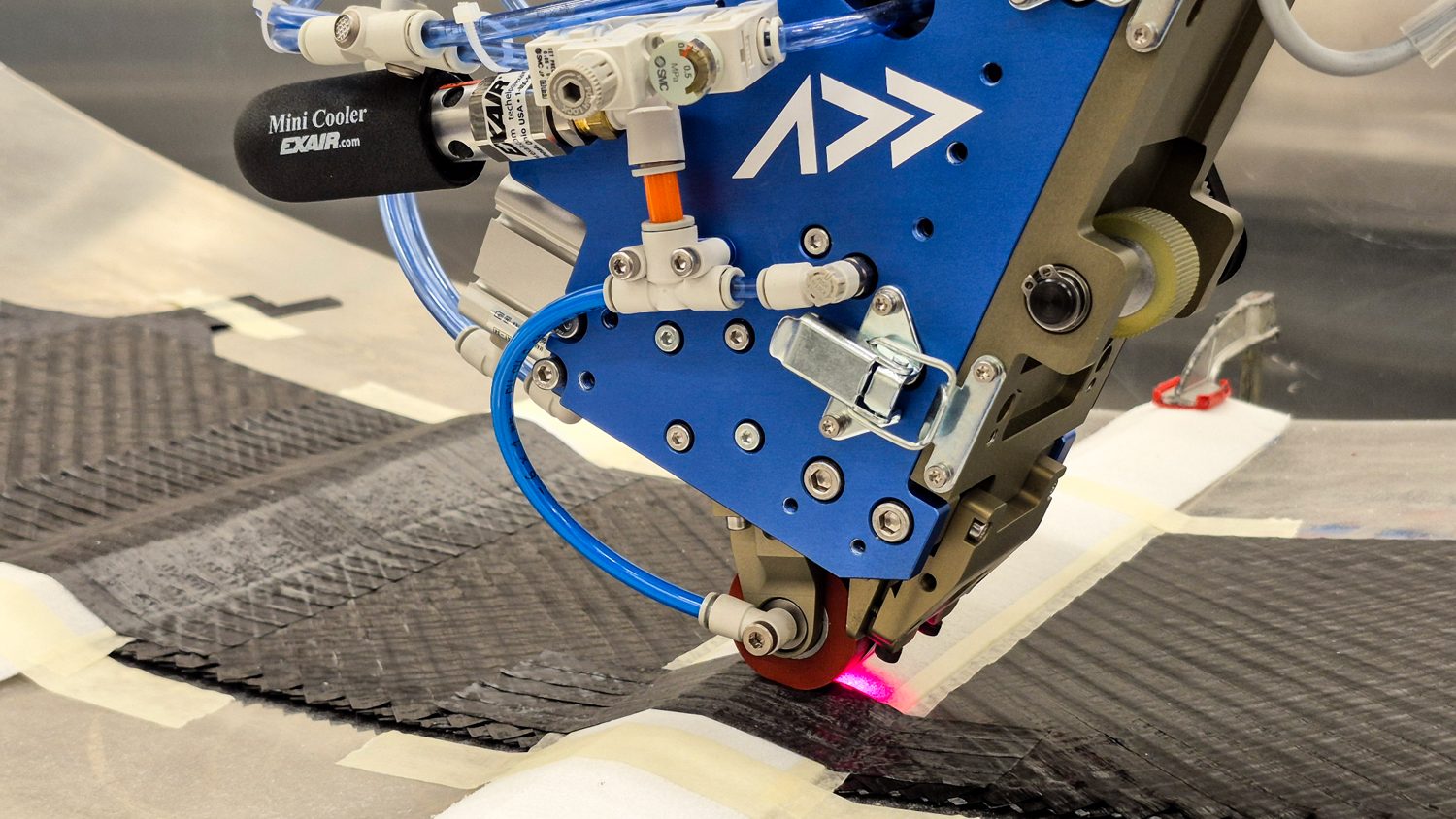
An Addcomposites AFP-XS head placing carbon fibre onto a curved tool, with the compaction roller in contact. Automated fibre placement delivers the repeatable, compacted and traceable layup that manual hand layup and vacuum bagging can't match at production rate. Photo: Addcomposites.
The honest caveat about recycled fibre and automation
Pyrolysis-recovered reinforcement typically comes back as fabric or discontinuous fibre, not as the continuous, slit tape or tow that an AFP head consumes. So the direct path is not “drop recycled fibre into an AFP machine tomorrow.” The more realistic near-term picture is hybrid: virgin tow placed by AFP in the primary load paths where continuity and orientation control matter most, with recycled material used where the data (like this study) supports it. For teams building that kind of program, our default recommendation remains the AFP-XS as the accessible entry point for developing and qualifying layup strategies, with the AFP-X — a four-tow head that delivers roughly four times the deposition rate — where higher production volume or more complex geometries justify it.
Simulation-led validation is the transferable lesson
The strongest methodological idea in this paper is the discipline of validating the model on a cheap, well-understood material before trusting it on the material you actually care about. That workflow — tie the digital model to physical coupons, then let the validated model do the heavy comparison — is exactly the loop that pays off in AFP process development, where every additional validated model reduces the number of expensive physical trials you need.
Our overall read: this is a well-constructed feasibility study that gives the recycled-CFRP-for-structures conversation a concrete, part-level anchor it did not have before. It does not certify anything, and the authors would be the first to say so. But it does exactly what a good TRL-4 result should: it earns the material a seat at the next table.
Read the Research
- Bouman, N.; Marques, S.S.L.; Sebbe, N.P.V.; Gerritse, A.; Bernardi, H.H.; Menezes, W.M.M.; da Silva, F.J.G.; Matsushima, J.T.; Giovanetti, L.; Sales-Contini, R.d.C.M. “Advancing Sustainability in Aerospace: Evaluating the Performance of Recycled Carbon Fibre Composites in Aircraft Wing Spar Design.” Journal of Composites Science 2025, 9, 384. doi.org/10.3390/jcs9080384. Open access, published 22 July 2025, licensed under CC BY 4.0 (creativecommons.org/licenses/by/4.0/).
- Sales-Contini, R.C.M. et al. “Mechanical Strength and Surface Analysis of a Composite Made from Recycled Carbon Fibre Obtained via the Pyrolysis Process…” Materials 2024, 17, 423 — the authors' own prior pyrolysis study. Open-access full text: pmc.ncbi.nlm.nih.gov/articles/PMC10817289/.
- Global Market Insights, 2025 aerospace-composite-recycling analysis — cited for the thermal (pyrolysis) segment and end-of-life aircraft component figures.
- Advanced Composites Engineering (recycled-fibre supplier) — cited for the CO2 emissions and material cost reduction figures for recycled versus virgin carbon fibre.
- Vartega, ELG Carbon Fibre and other recyclers cited in Carbon Fiber Recycling from Aerospace Composites Market coverage (2025), for industry context on where recovered aerospace fibre is currently used.
This article is an independent editorial summary and commentary produced by Addcomposites. It is not affiliated with, reviewed by, or endorsed by the study's authors or their institutions. Figures reproduced from ref. 1 are used under CC BY 4.0 and are credited individually. The supporting market sources are separately published works, named inline above; none were reviewed or endorsed by Addcomposites. Infographics are our own visualisations of data tabulated or reported in ref. 1, and are not reproductions of any figure from the paper.
