The 2026 State-of-the-Industry Review: Where CFRP Actually Earns Its Place in a Wind Blade, and Where GFRP Still Wins
A blade has to be light enough to spin, stiff enough not to strike its own tower, and durable enough to survive over a hundred million fatigue cycles. A June 2026 review works through the material trade-off across the whole structure — and is unsentimental about where carbon fiber earns its cost, and where glass fiber still wins on economics.
A wind turbine blade is one of the least forgiving structures in modern engineering. It has to be light enough to spin, stiff enough not to strike its own tower, and durable enough to survive decades of relentless flexing in wind, rain, salt, and temperature swings. Getting the material choice wrong at any point along its length is expensive, and sometimes catastrophic.
A June 2026 open-access review in the Journal of Energy and Power Technology, authored by Dudu Mertgenç Yoldaş, Senai Yalçinkaya, and Mehmet Fatih Yoldaş, works through that material-selection problem across the whole blade rather than fixating on the headline component. It weighs carbon fiber-reinforced polymer (CFRP) against glass fiber-reinforced polymer (GFRP), ranks the main manufacturing routes against each other, and lays out why blade designers join composite parts the way they do. What makes it useful as a single briefing document is that it is unsentimental in both directions: it is clear about where carbon fiber earns its keep, and equally clear about where glass fiber still wins the argument on economics.
This post walks through the review's core findings, visualizes the underlying data with original diagrams, and then, in clearly fenced editorial sections, offers Addcomposites' own perspective on what all of this means for automated fiber placement. Throughout, the boundary between what the paper reports and what is our commentary is kept deliberately visible.
A blade is a fatigue problem before it is anything else
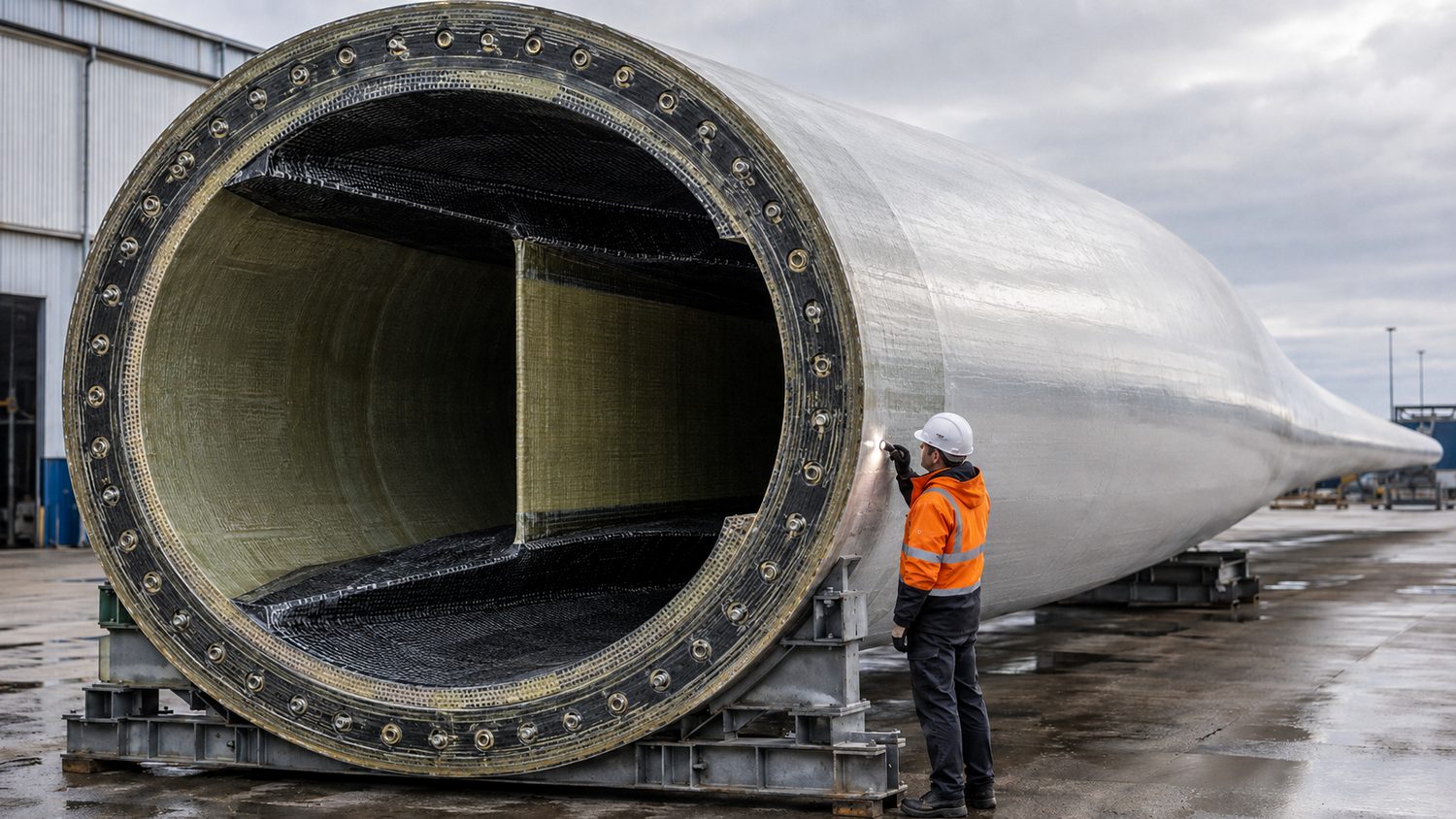
Composite blade root section under inspection, showing the embedded root-stud ring, spar caps, and central shear web that carry the blade's bending loads — the technician gives scale to a structure built to survive over 100 million fatigue cycles. Illustrative render.
Before comparing materials, it helps to understand what the material has to survive. According to the review, a blade in service works through more than a hundred million loading cycles across a typical design life of twenty to thirty years. Those cycles come from a combination of aerodynamic pressure, gravity swinging the blade around each rotation, and the centrifugal pull of the rotor. The paper singles out fatigue behavior as the design parameter that dominates everything else. Two spots do most of the failing, according to the review: the root, and wherever parts are bonded together, both places where stress piles up locally.
That framing matters, because it reorders the usual instinct to reach for the strongest or stiffest material. What a blade actually needs is a material that can absorb a hundred-million-cycle beating without progressively coming apart. The review's headline claim about carbon fiber is grounded in exactly this endurance argument rather than in raw strength alone.
The Loading Problem A Blade Must Survive
Design envelope for a modern wind-turbine blade, per the 2026 materials review
Diagram above: original visualization by Addcomposites of loading conditions and failure locations described in Yoldaş et al., JEPT 2026.
The material numbers, side by side
The review compiles rigidity and strength figures for the candidate blade materials into a single comparison. Rather than reproduce that table, we have plotted the paper's reported ranges as bar charts so the trade-off is visible at a glance. The two properties that matter most here are Young's modulus (stiffness) and density (mass penalty), because the whole case for carbon fiber rests on the ratio between them.
Stiffness vs. Mass: CFRP vs. GFRP vs. Metals
Reported property ranges for wind-turbine-blade structural materials (2026 review). Bar length = upper bound of range, scaled to the stiffest / densest material in each panel.
Young’s Modulus (GPa, upper bound / 210 GPa)
Density (kg/m³, upper bound / 7850 kg/m³)
CFRP sits HIGH on stiffness but LOW on mass.
Steel is stiffer in absolute terms but roughly 5x heavier.
⇒ Carbon’s advantage is stiffness PER UNIT MASS, not raw stiffness.
Diagram above: original bar-chart visualization by Addcomposites of the material property ranges reported in Table 2 of Yoldaş et al., JEPT 2026.
The paper reports carbon fiber composites with tensile strength spanning roughly 1000 to 3000 MPa and a “very high” fatigue rating, against glass fiber's 600 to 1200 MPa and a “high” rating. Steel and aluminum, the materials that early blades were built from, carry a density penalty that makes them unworkable at modern blade lengths. Balsa wood appears in the table not as a structural competitor but in its usual role as a lightweight sandwich core.
The authors are explicit that carbon's superiority in stiffness-to-weight and strength-to-weight is what unlocks the practical benefits downstream. As the paper puts it, these ratios enable weight reductions “of 20-30% in critical blade components such as spar caps.” That is one of the few places we quote the review directly, because the specific figure is the crux of the whole material argument.
Where CFRP earns its place
Here is the review's central, and most commercially useful, distinction. Carbon fiber does not go everywhere in a blade. It goes into the spar caps and other load-critical regions, and the reason is a chain of consequences that all follow from taking mass out of the right place.
When carbon fiber replaces glass in the spar cap, the paper reports the blade sheds roughly a fifth to a third of the weight in that component. That reduction is not just about a lighter blade for its own sake. Taking mass out of the spine eases the gravitational load the blade swings through each rotation, calms the aeroelastic behavior that long blades are prone to, and, because the rotor can then be lengthened, pulls more energy from the same wind. The review presents these as the linked benefits that follow from concentrating carbon where it counts.
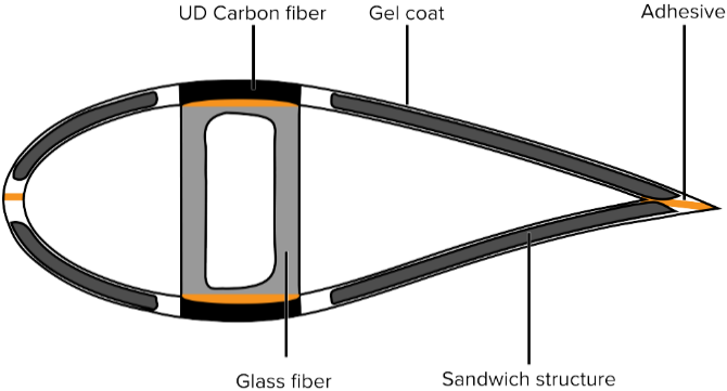
Generic cross-section of a wind turbine blade, showing the UD
carbon fiber spar caps top and bottom, the glass fiber shell
skins, the sandwich core structure, and the structural adhesive
bonding the profile — carbon concentrated in the
load-carrying spar caps, glass across the aerodynamic shell.
Figure 22 from: Yoldaş DM, Yalçinkaya S, Yoldaş MF. “Use of
Composite Materials in Wind Turbine Blades: A Comprehensive
Review.” Journal of Energy and Power Technology
2026, 8(2), 2602010, p. 17 (Fig. 22, as cited in the review from
ref. [98]).
doi.org/10.21926/jept.2602010
— © 2026 by the authors. Licensed under CC BY 4.0 (creativecommons.org/licenses/by/4.0/).
The spar caps run lengthwise along the blade and carry the flapwise bending load, meaning the load that tries to bend the blade back toward the tower. As the review describes it, the two bending modes split between components: the spar caps take the flapwise load, and the shell handles edgewise. That division of labor is precisely why carbon is worth its cost in one region and not the other: the spar cap is where stiffness-to-weight buys the most, so that is where the expensive material is concentrated.
Where GFRP still wins
The catch is price. The review is direct that carbon fiber remains expensive enough that its use is deliberately selective rather than universal. The review's account of glass fiber is that it dominates on economics: good enough mechanically, and cheap enough to cover the blade's large surface area without the material bill running away.
So the picture the paper paints is not “carbon is replacing glass.” It is a hybrid strategy: glass fiber across the bulk shell where affordability dominates, carbon fiber concentrated in the load-critical spine where structural payoff justifies the spend. The authors present this hybrid GFRP/CFRP approach as the arrangement that best balances cost against performance, and the paper's own milestone timeline notes a recent large floating turbine adopting a hybrid glass/carbon structure to hit high stiffness-to-weight targets.
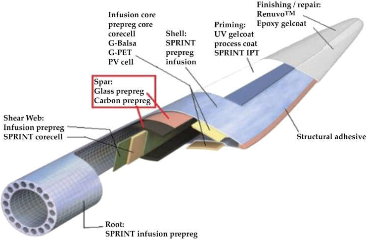
Cutaway of a wind turbine blade's material configuration,
showing the glass prepreg and carbon prepreg in the spar, the
SPRINT prepreg-infusion shell, the G-Balsa, G-PET and PVC core
cells, the SPRINT infusion prepreg root, and the structural
adhesive — the hybrid glass/carbon layout mapped across the
blade.
Figure 33 from: Yoldaş DM, Yalçinkaya S, Yoldaş MF. “Use of
Composite Materials in Wind Turbine Blades: A Comprehensive
Review.” Journal of Energy and Power Technology
2026, 8(2), 2602010, p. 24 (Fig. 33, as cited in the review from
ref. [107]).
doi.org/10.21926/jept.2602010
— © 2026 by the authors. Licensed under CC BY 4.0 (creativecommons.org/licenses/by/4.0/).
The Hybrid Logic Along the Blade Span
Carbon where load is critical, glass across the bulk — root to tip
Diagram above: original visualization by Addcomposites of the hybrid material strategy and the root/mid-span/tip regional breakdown described in Yoldaş et al., JEPT 2026.
The blade as a structure: shell, spar caps, shear webs
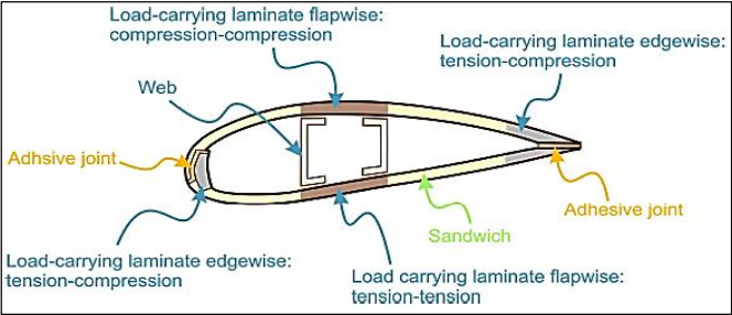
Cross-section of a wind turbine blade's internal beam structure,
showing the flapwise load-carrying laminate in compression on
the suction side and tension on the pressure side, the edgewise
tension-compression laminates at the leading and trailing edges,
the central web, the sandwich panels, and the adhesive joints
— the internal beam that carries the vast majority of
operational loads.
Figure 25 from: Yoldaş DM, Yalçinkaya S, Yoldaş MF. “Use of
Composite Materials in Wind Turbine Blades: A Comprehensive
Review.” Journal of Energy and Power Technology
2026, 8(2), 2602010, p. 19.
doi.org/10.21926/jept.2602010
— © 2026 by the authors. Licensed under CC BY 4.0 (creativecommons.org/licenses/by/4.0/).
The review devotes considerable space to how the pieces fit together, because material choice only makes sense in the context of load paths. A modern blade, as the authors describe it, is built from two main structural systems. The outer shell is the aerodynamic skin, the curved suction and pressure faces the air actually flows over. Tucked inside is the spar, an internal beam that funnels the mechanical load down to the root: its upright walls are the shear webs, and its flat top-and-bottom flanges are the spar caps.
In flight the two faces load up oppositely, the paper explains: the suction surface is squeezed while the pressure surface is stretched. From the shell, that load hands off to the spar caps, which take on the main structural burden, while the shear webs keep the two shell faces from shifting against each other and hold the cross-section from collapsing.
Diagram above: original visualization by Addcomposites of the load-transfer sequence described in Yoldaş et al., JEPT 2026.
A finished blade, the review notes, is two half-shells glued along their seams into a single closed aerofoil, which brings the discussion to the two process questions the paper treats as decisive: how the laminate is made, and how the parts are joined.
Manufacturing: the review ranks vacuum infusion above hand lay-up
The paper surveys the common composite production routes, hand lay-up, vacuum bagging, and vacuum infusion, and then makes a clear ranking for large-scale blades. Vacuum infusion comes out on top, and the reasons the authors give are specific rather than vague. Drawing the resin through a dry fiber stack under vacuum leaves fewer trapped air pockets and wets the fibers out more evenly, and the review links that directly to a cleaner, more dependable laminate.
That is a quality-consistency argument, not a strength-of-materials argument. The point is not that infusion produces a fundamentally different fiber; it is that the process controls the defects, the voids, the dry spots, the resin-rich pockets, that undermine fatigue life in a structure expected to survive a hundred million cycles.
2026 Materials Review · Wind Blade Manufacturing
Manufacturing Quality Ladder
Ranked qualitatively by laminate consistency, highest to lowest — the review assigns no numeric scores; bar heights are a stair-step ordering, not measured values.
- Lowest void content
- Uniform resin distribution
- Improved over open lay-up
- More prone to voids and misalignment
Process control →
Qualitative ordering per the 2026 review — not a measured or numerically scored comparison.
Diagram above: original visualization by Addcomposites of the relative manufacturing-quality ranking described in Yoldaş et al., JEPT 2026. The paper does not assign numeric scores; the bars represent the qualitative ordering the authors describe.
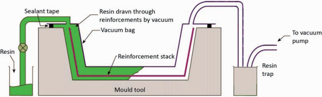
Schematic of the vacuum infusion process, showing resin drawn
from the resin source through the dry reinforcement stack under
vacuum-bag pressure, across the mould tool, and into the resin
trap ahead of the vacuum pump — the route that lowers void
content and evens out resin distribution in large blade
laminates.
Figure 38 from: Yoldaş DM, Yalçinkaya S, Yoldaş MF. “Use of
Composite Materials in Wind Turbine Blades: A Comprehensive
Review.” Journal of Energy and Power Technology
2026, 8(2), 2602010, p. 25 (Fig. 38, as cited in the review from
ref. [113]).
doi.org/10.21926/jept.2602010
— © 2026 by the authors. Licensed under CC BY 4.0 (creativecommons.org/licenses/by/4.0/).
The review's own reasoning for ranking infusion over hand lay-up is a consistency argument: fewer voids, more uniform resin, more repeatable laminate. That same logic is the foundation of the case for automated fiber placement in the load-critical CFRP regions the paper is describing. AFP lays down carbon tow along a programmed path with controlled compaction, which removes the manual variability that drives void content and fiber misalignment in the first place. Where a spar cap is the component carrying flapwise bending across a hundred million cycles, process repeatability is not a nicety, it is the fatigue-life lever. For teams building large blade spar structures, our AFP-X system is designed for exactly this class of large, load-critical part, while AFP-XS offers an accessible entry point for R&D and smaller-scale carbon components, both driven through the same AddPath toolpath environment. To be explicit: automated fiber placement is not discussed in the paper. The authors compare hand lay-up, vacuum bagging, and infusion only. What we are doing here is extending their stated consistency logic one step further, as our own commentary.
Joining: adhesive bonding over mechanical fastening
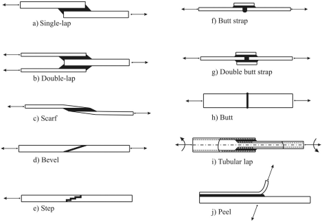
Catalogue of typical engineering adhesive joint geometries
— single-lap, double-lap, scarf, bevel, step, butt strap,
double butt strap, butt, tubular lap, and peel — the
configurations that determine how load and peel stresses
distribute across a bonded joint.
Figure 41 from: Yoldaş DM, Yalçinkaya S, Yoldaş MF. “Use of
Composite Materials in Wind Turbine Blades: A Comprehensive
Review.” Journal of Energy and Power Technology
2026, 8(2), 2602010, p. 27 (Fig. 41, as cited in the review from
ref. [122]).
doi.org/10.21926/jept.2602010
— © 2026 by the authors. Licensed under CC BY 4.0 (creativecommons.org/licenses/by/4.0/).
The review's second process verdict concerns how composite parts are joined, and it comes down in favor of adhesive bonding for blade structures. The authors' case is that a glued joint carries its load smoothly over the whole bonded face, sidestepping the sharp local peaks a bolt or rivet leaves behind. Fastening a composite mechanically means drilling into it, and each hole cuts fibers and plants a stress spike precisely where the material most needs to stay continuous.
The review does not present adhesive bonding as flawless. It flags that these joints give way comparatively easily under peel loading, with the break running along the bond line, either where the adhesive meets the part or through the adhesive layer itself. To capture the benefits of both approaches, the paper points to hybrid joining, combining adhesive with mechanical fasteners, as a way to raise load-carrying capacity and reliability.
Stress spikes at each drilled hole; fibers are cut — discontinuity.
Stress spread evenly across the bond area — sensitive to peel at the bond edges.
Diagram above: original visualization by Addcomposites of the joint stress behavior described in Yoldaş et al., JEPT 2026.
The damage mechanisms the design is fighting
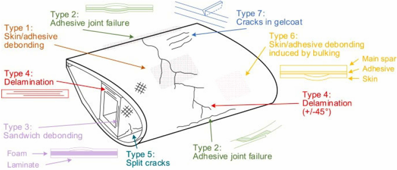
The seven damage types mapped onto a wind turbine blade shell
structure — skin/adhesive debonding, adhesive joint
failure, sandwich debonding, delamination, split cracks,
debonding induced by buckling, and gelcoat cracks — the
failure modes that cyclic loading meeting local stress risers
drives most dangerously at the root and spar-web junctions.
Figure 39 from: Yoldaş DM, Yalçinkaya S, Yoldaş MF. “Use of
Composite Materials in Wind Turbine Blades: A Comprehensive
Review.” Journal of Energy and Power Technology
2026, 8(2), 2602010, p. 26 (Fig. 39, as cited in the review from
ref. [118]).
doi.org/10.21926/jept.2602010
— © 2026 by the authors. Licensed under CC BY 4.0 (creativecommons.org/licenses/by/4.0/).
Tying the material and process discussions together, the review catalogs the failure modes that blade designers are ultimately designing against: delamination between plies, fiber breakage, adhesive debonding, matrix cracking, and surface cracking in the gel coat. The common thread the authors draw is repetitive loading meeting a local stress riser, most dangerously at the root and at the junctions where the spar meets its webs.
This is the through-line of the whole paper. Every material and process choice, carbon in the spar cap, glass in the shell, infusion over lay-up, adhesive over bolts, traces back to controlling where and how fast these damage modes initiate. The recurring theme is that predicting the stress distribution accurately and tailoring fiber orientation to the load path is what separates a blade that lasts thirty years from one that fails early.
Diagram above: original visualization by Addcomposites summarizing the damage mechanisms and design responses discussed in Yoldaş et al., JEPT 2026.
Our take on what this means for AFP manufacturers
The following is Addcomposites editorial commentary, not a conclusion of the paper.
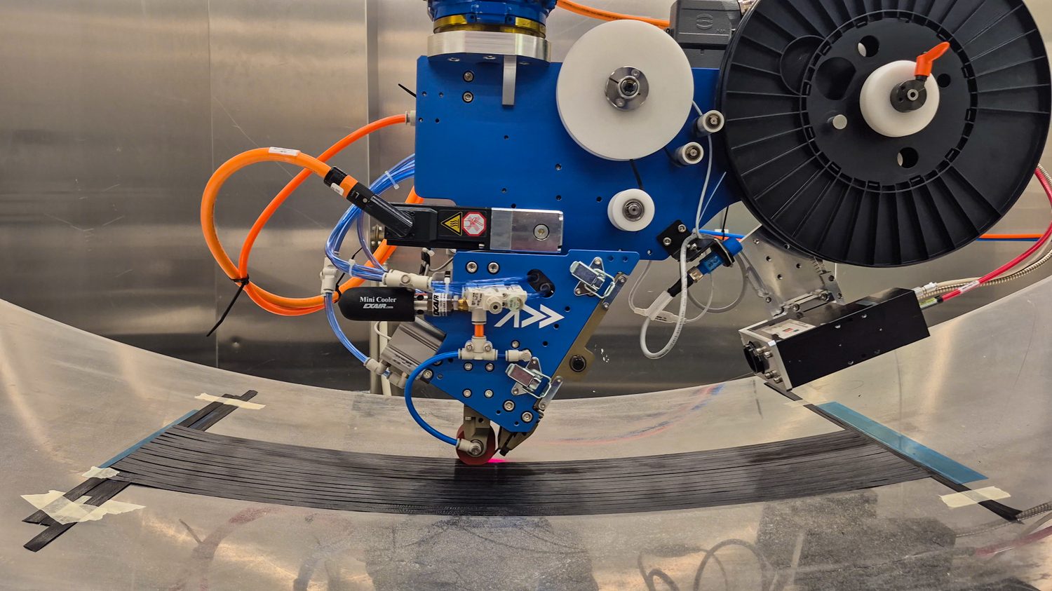
Addcomposites' AFP-XS placing carbon fiber tow under controlled compaction and heat on a curved tool — programmable, repeatable placement for load-critical carbon components.
The most valuable thing about this review is that it is honest about carbon fiber's limits. The story is not blanket CFRP adoption; it is cost-driven selectivity, carbon concentrated where flapwise bending demands stiffness-to-weight, glass holding the affordable bulk. That is the reality blade OEMs are actually planning around, and it is the reality any AFP business pitching into the wind supply chain has to speak to.
Read that way, the paper hands AFP a ready-made external argument. Its authors rank vacuum infusion above hand lay-up specifically because infusion controls void content and resin distribution, in other words, because it is more consistent. Consistency is the entire value proposition of automated fiber placement in the load-critical carbon regions the paper describes. If the industry already accepts that infusion beats hand lay-up on consistency grounds, then the same consistency logic points, with even more force, toward programmable fiber placement for the spar-cap-class parts where fatigue life is set. AFP-X targets those large, load-critical structures; AFP-XS lowers the barrier for teams building and qualifying smaller carbon components; and AddPath gives both a single programmable path-planning workflow so the process is repeatable part to part.
None of this is a claim the review makes. The authors do not mention AFP, Addcomposites, or any specific equipment, and nothing here should be read as their endorsement. It is our extension of a consistency argument they make on their own terms, offered as one manufacturer's reading of a genuinely useful state-of-the-industry document.
If you're scoping a large-scale, load-critical spar-cap programme and want to talk through where programmable, repeatable carbon placement fits your fatigue-life budget, get in touch with the Addcomposites team →
Contact Us for a ConsultationThe bottom line
The review's own conclusion lands on a balanced note that resists easy slogans. As the authors frame it, fiber-reinforced polymers displaced metal because blades grew too long for steel and aluminum to remain viable. Within the composite world, carbon fiber delivers a decisive stiffness-to-weight and fatigue advantage that justifies its cost in spar caps and other load-critical regions, cutting component weight by twenty to thirty percent, while glass fiber remains the economical default across the shell. Vacuum infusion is the manufacturing route the authors favor for large blades on consistency grounds, and adhesive bonding, ideally reinforced by hybrid joining where reliability demands it, is their preferred way to hold the structure together. The unifying thread is fatigue: for a structure facing more than a hundred million load cycles, quality and consistency are not finishing touches, they are the design.
Read the Research
- Yoldaş DM, Yalçinkaya S, Yoldaş MF. Use of Composite Materials in Wind Turbine Blades: A Comprehensive Review. Journal of Energy and Power Technology 2026, 8(2), 2602010 (pp. 1–36). doi.org/10.21926/jept.2602010. Open Access, licensed under CC BY 4.0 (creativecommons.org/licenses/by/4.0/).
This article is an independent editorial summary and commentary produced by Addcomposites. It is not affiliated with, reviewed by, or endorsed by the study's authors or their institutions. Figures reproduced from ref. 1 are used under CC BY 4.0 and are credited individually. Infographics are our own visualisations of data reported in ref. 1, and are not reproductions of any figure from the paper.
