A CFRP Cockpit Console Cuts Weight by 40% Over Aluminium Without Giving Up Vibration Damping
A Wuhan University of Technology team rebuilt an aerospace display and control console in carbon fibre, cut 28 kg out of its load-bearing structure, then ran it on a shaker for an hour and went looking for what broke. Something did.
Aircraft weight budgets get fought over gram by gram in the primary structure, then quietly surrendered in the cabin. Racks, brackets, enclosures, consoles: still bent aluminium sheet, most of the time. Not because anyone thinks that is optimal, but because the tooling is cheap, the parts are not flight-critical, and nobody wants to be the engineer who lightweighted a pilot's display mount and then watched it ring.
A paper published in Polymers (MDPI) on 19 February 2026 takes that problem head-on. Jun Rao, Qiaoxin Zhang, Yu Feng, Meng Wei and Wentao Yang, working across Wuhan University of Technology and Hubei Anxin Intelligent Technology Co., Ltd., rebuilt an aerospace display and control console (DCC) in carbon fibre reinforced polymer and then went looking for reasons it might not work. The number they report is a structural mass cut of roughly 40% against the metal original, with stiffness, strength and vibration behaviour all still inside requirement.
Our view is that the mass figure is not the most valuable thing in the paper. What makes it worth reading is that the team put the finished console on a shaker for an hour, took it off, looked closely at the joints, and published what they found there, including damage the simulation had not anticipated. Papers that report the thing that went slightly wrong are more useful than papers that do not.
What follows is a walk through the study, then our own commentary on what it implies for anyone building composite cabin hardware with automated fibre placement.
A note on boundaries: everything attributed to “the paper,” “the authors,” or “the study” is the researchers' work. Anything under “Our perspective” is Addcomposites' commentary. The authors did not review, endorse, or validate this article or our products.
The baseline: a 133 kg metal console
The reference article is a conventional aluminium alloy console standing roughly 1560 mm tall. Its total mass, as reported, is 133 kg. Strip away the displays, keyboard, electronics and the dampers at floor level, and 69.5 kg of that is load-bearing structure.
That 69.5 kg is the number the redesign attacks. The payload stays put; the frame underneath it is what changes.
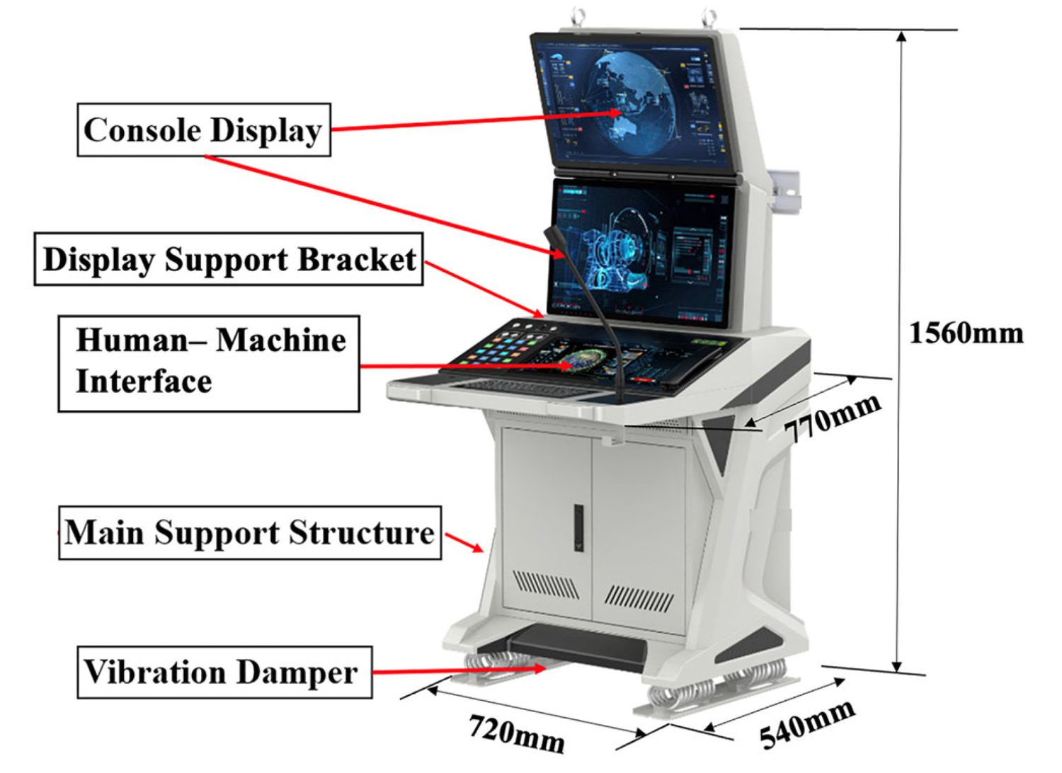
The aluminium original, dimensioned at 1560 mm tall on a 720 ×
540 mm footprint, with the display, support bracket, operator
interface, main structure and floor dampers labelled.
Figure 2 from: Jun Rao, Qiaoxin Zhang, Yu Feng, Meng Wei, Wentao
Yang. “Dynamic Characterization and Damping Enhancement
Mechanism of Carbon Fiber Reinforced Hybrid Structures for Aerospace
Electronics.” Polymers 2026, 18, 516.
https://doi.org/10.3390/polym18040516
— © 2026 by the authors. Licensed under CC BY 4.0 (https://creativecommons.org/licenses/by/4.0/).
The composite version comes in at approximately 41.5 kg.
Rao et al., Polymers 2026, 18, 516
Load-bearing structure: 69.5 kg → 41.5 kg
Structural mass only. The 133 kg total console includes displays, keyboard, electronics and floor dampers, which the redesign leaves untouched.
Values reported by Rao et al., Polymers 2026, 18, 516.
Material, and where the leverage comes from
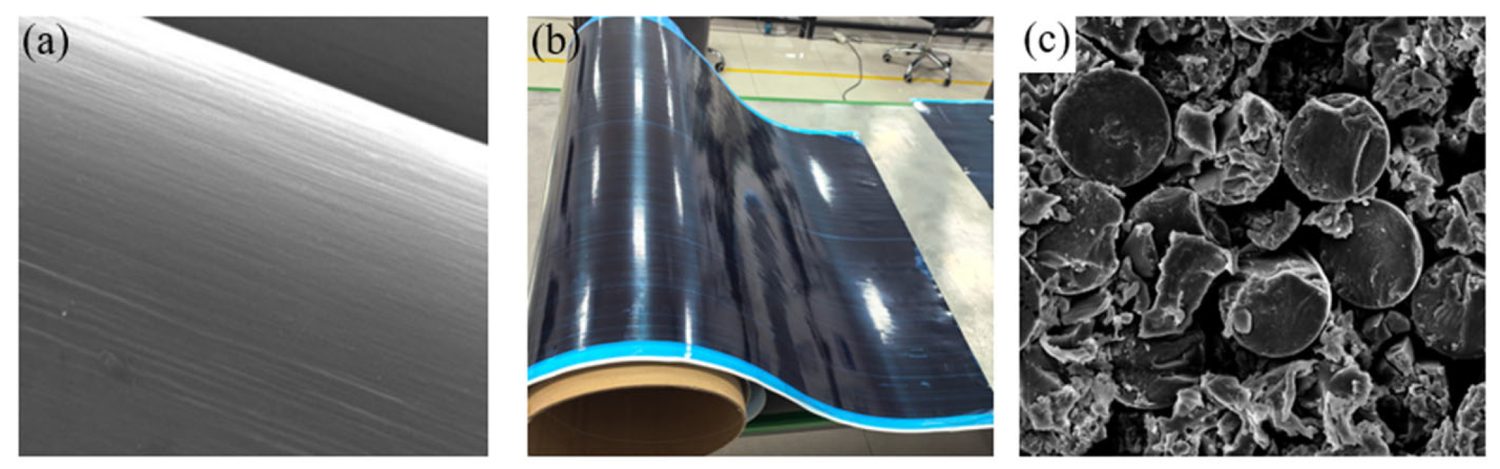
The composite as delivered: aligned carbon filaments at
magnification, a roll of T300-grade prepreg, and a polished laminate
cross-section showing individual fibres set in cured resin.
Figure 1 from: Jun Rao, Qiaoxin Zhang, Yu Feng, Meng Wei, Wentao
Yang. “Dynamic Characterization and Damping Enhancement
Mechanism of Carbon Fiber Reinforced Hybrid Structures for Aerospace
Electronics.” Polymers 2026, 18, 516.
https://doi.org/10.3390/polym18040516
— © 2026 by the authors. Licensed under CC BY 4.0.
The composite is a T300-grade prepreg from Zhongfu Shenying Carbon Fiber Co., Ltd. It runs 57/43 fibre to resin by volume, and a single uncured ply measures 0.2 mm nominal. Aluminium 6061 does not disappear from the design; it gets confined.
The stiffness and density figures the authors tabulate explain most of the outcome:
Table 1 — engineering constants
Where the specific stiffness comes from
Aluminium 6061 against the T300 / YPH-308 carbon-epoxy prepreg, as tabulated by Rao et al.
Engineering constants as tabulated by Rao et al., Polymers 2026, 18, 516. Aluminium is isotropic: the paper lists one value and the repeated entries above are ours. The three derived ratios are our arithmetic on the tabulated figures.
Our arithmetic on those figures: density alone favours the composite by about 1.69 to one. Divide axial modulus by density and the composite comes out near 78 against roughly 26 for the metal, close to three times the specific stiffness along the fibre. That ratio is the whole lever. It is also directional, which is why the ply schedule matters more here than the material datasheet does.
Architecture: three pieces, quasi-isotropic, 5 mm walls
Rather than one welded metal shell, the authors break the console into three separately moulded pieces. There is the frame that carries load, the arm that holds the display, and the panel the operator touches. The reason given is fibre continuity and ease of manufacture: each piece can be laid up without the fibre path having to negotiate someone else's geometry.
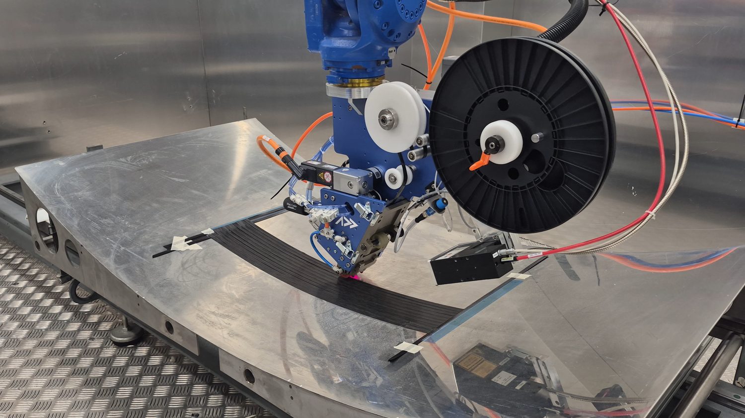
The Addcomposites AFP-XS head placing tow along a contoured tool, the band following the surface as one continuous path. Fibre direction is set by the deposition programme rather than by how a laminator negotiates the curve.
Walls are 5 mm. The stack is quasi-isotropic, apportioned 25% at 0°, 25% at 90° and half the plies split between +45° and −45°. A 3K twill fabric sits outermost, chosen on cosmetic grounds, over a repeating unidirectional stack running [0/45/90/−45]s.
Laminate architecture
A 5 mm quasi-isotropic wall, twill-faced
Layup schedule as described by Rao et al., Polymers 2026, 18, 516.
Outer surface
Inner surface
The ply count is our estimate: at 0.2 mm per uncured ply a 5 mm wall implies roughly 25 plies, about three passes through the eight-ply block plus the woven face. The paper gives prepreg thickness rather than cured thickness, and consolidation moves the number.
At 0.2 mm per uncured ply, a 5 mm wall implies somewhere around 25 plies, or roughly three passes through the eight-ply block plus the woven face. That count is our estimate and should be treated loosely: the paper gives prepreg thickness rather than cured thickness, and consolidation moves the number.
One process detail stands out, and it is the kind that only appears when the authors have actually made the part. Where the frame turns a corner, they pack the radius with rolled unidirectional rod stock, so the plies neither bridge the bend nor leave a resin pocket sitting in the corner.
Radius defects are a chronic failure source in bent composite frames. Seeing the mitigation written into the process description rather than discovered in the discussion section is a good sign.
Metal survives wherever precision or load demands it. The design section names two places: the fittings the displays bolt to, and the angled pads the assembly sits on. The finite element description later keeps the shock absorbers and hinges metallic as well. This is a hybrid, not a substitution.
Making it
Curing happens in an autoclave. The authors weighed that against press moulding and resin transfer, and went with the autoclave for through-thickness bond quality and for holding dimensional accuracy on awkward shapes.
The cycle is staged rather than single-ramp. Pressure comes on at 0.4 MPa once the part reaches 80 °C and holds until shortly before cool-down; the full cycle runs about 300 minutes. Temperature climbs through holds at 80, 115, 135 and 145 °C, giving the resin time to crosslink at each step. Cool-down is deliberately restrained at 3 °C per minute, which the authors tie to keeping residual thermal stress down.
Autoclave cure cycle
Four holds, then a restrained descent
Cure schedule as described by Rao et al., Polymers 2026, 18, 516. Recreated from the paper's Figure 3.
Pressure is applied once the part reaches 80 °C, roughly twenty minutes in, and released shortly before cool-down; the full cycle runs about 300 minutes.
That controlled descent matters more on this part than it would on an all-composite one. Aluminium and carbon laminate shrink at very different rates, and every co-cured metal fitting is a place where that mismatch has to go somewhere.
Load introduction gets two treatments depending on severity. Where forces are heaviest, the metal fitting is abraded, sleeved in unidirectional fabric and cured in place as part of the laminate. Lower-load fittings take a simpler route: adhesive onto an abraded interface, with mechanical clamping holding position while the resin sets.
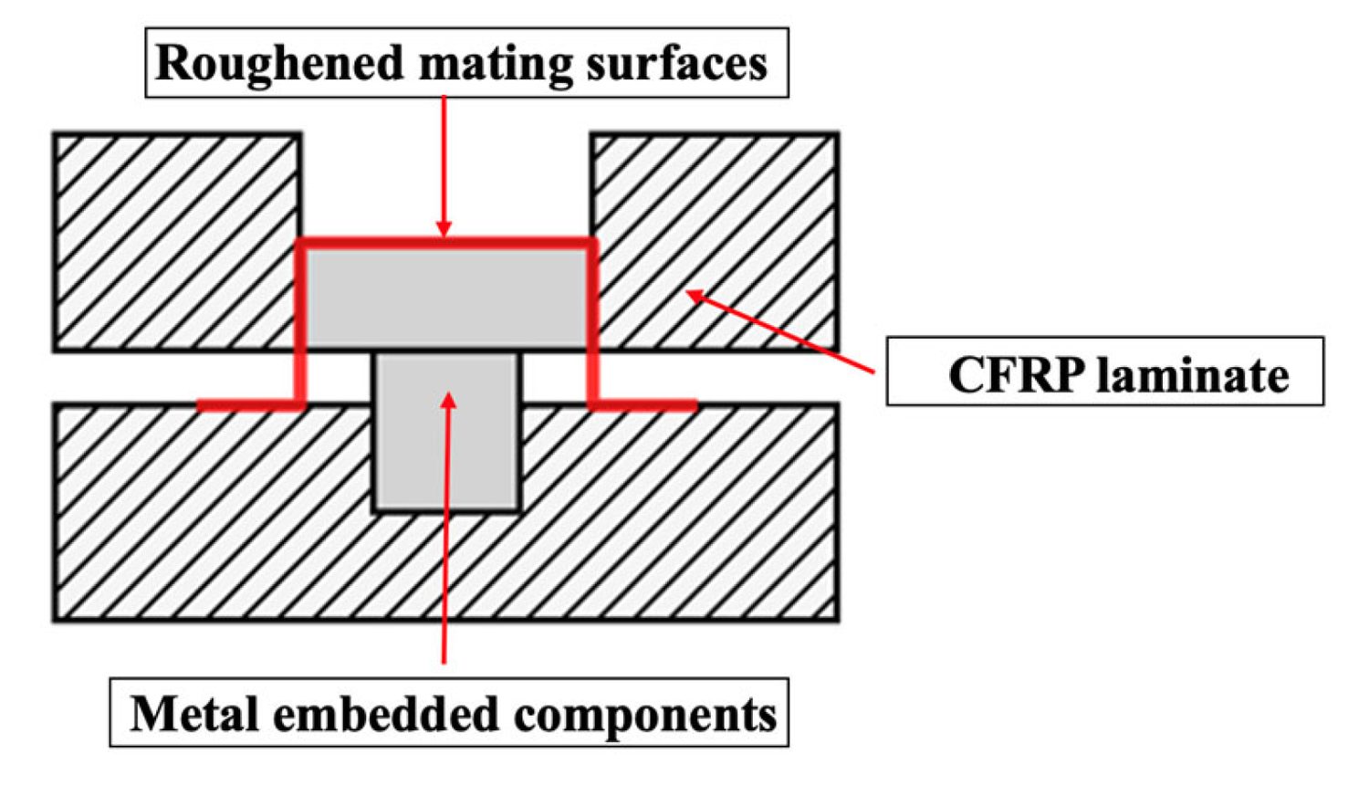
Section view of a load-introduction point: the metal insert sandwiched
between laminate plies, with the roughened bonding interfaces marked
in red.
Figure 4 from: Jun Rao, Qiaoxin Zhang, Yu Feng, Meng Wei, Wentao
Yang. “Dynamic Characterization and Damping Enhancement
Mechanism of Carbon Fiber Reinforced Hybrid Structures for Aerospace
Electronics.” Polymers 2026, 18, 516.
https://doi.org/10.3390/polym18040516
— © 2026 by the authors. Licensed under CC BY 4.0.
The damping argument
The authors open with the usual assertion that the resin gives the laminate more damping capacity than aluminium, but they do not leave it there. They go on to build the case out of strain energy.
Damping capacity is defined as energy lost over energy stored per cycle. From there the structural loss factor emerges as a weighted sum: every element contributes its directional loss factor, weighted by how much strain energy that element is holding. Two simplifications get applied. Transverse isotropy collapses several of the directional terms into pairs, and the through-thickness shear contribution is set aside on the grounds, citing earlier work, that its share of total structural damping is negligible. The loss factor then converts to a damping ratio through a standard relation.
The consequence is worth sitting with. Under this formulation the console's damping is not a property of the material at all. It is an average, weighted by where the strain energy happens to sit in a given mode. Move the ply ratio, thin the wall, relocate the bracket tie-in, and the damping moves with it. You cannot fix console vibration by changing the material alone; the geometry has to move with it.
The authors make exactly that point in their introduction, framing console vibration as a coupled material and structure problem rather than a substitution. What they do not do is close the loop. The framework needs a directional loss factor for every term, and no such value appears anywhere in the paper: Table 1 lists stiffness, Poisson ratios and density but no loss factors, and no damping ratio or strain energy split is reported for either console. The derivation is a method, not a measurement, and it cannot be reproduced from what is published. That is the largest gap in the work.
Simulation
Everything ran in ABAQUS 2025. Prepreg layers were represented with continuous shell elements on a swept mesh. Payload masses, the displays and electronics totalling 64 kg across four locations, were tied onto structural hard points through multi-point constraints rather than smeared into the shell, which would have stiffened the model artificially. The model was restrained rigidly where the console meets its dampers, and that restraint defines the constrained mode set. Small features such as chamfers and fastener holes were left out of the geometry.
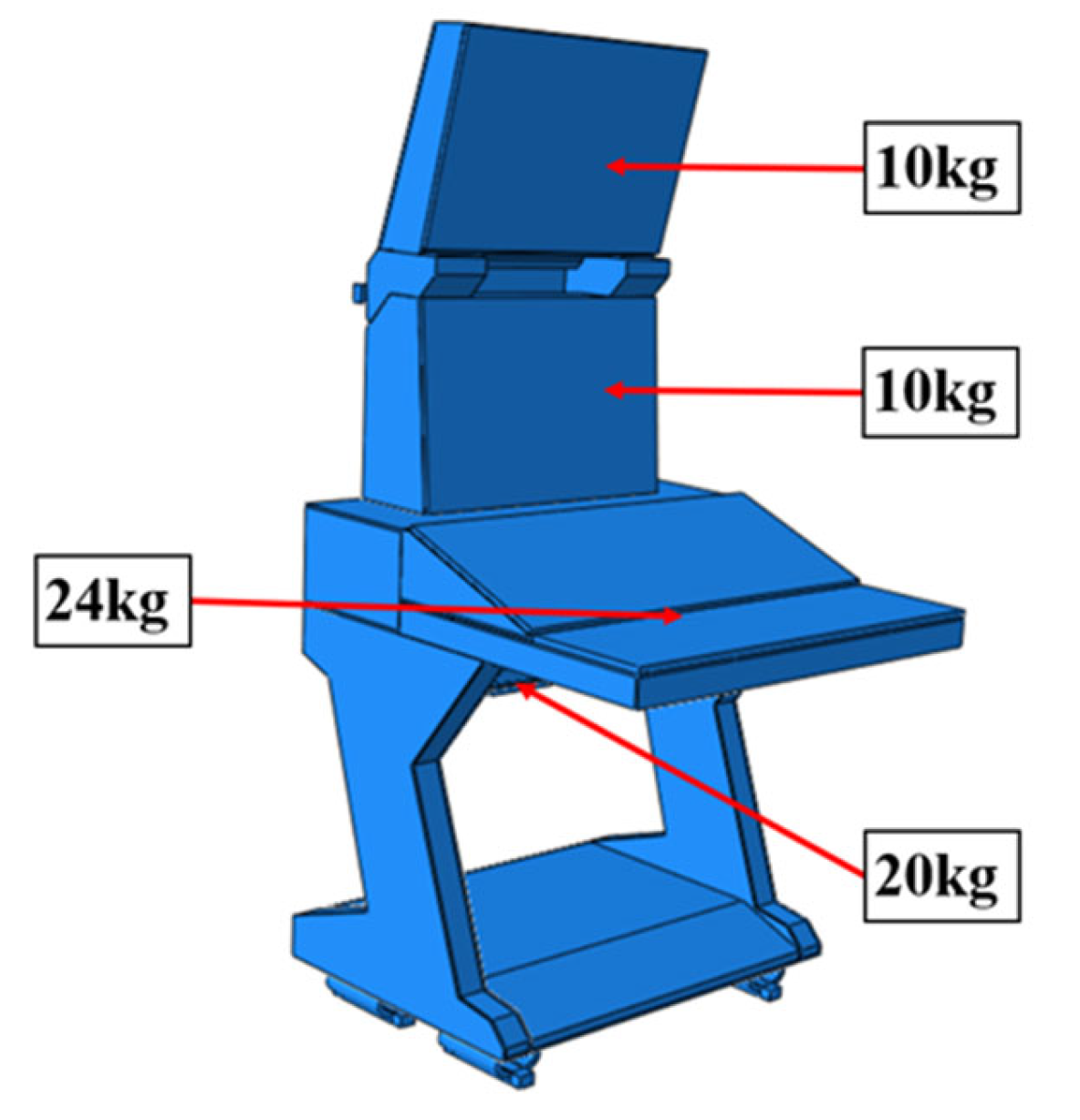
The meshed console model, with the electronics payload called out
where it is applied: 10 kg at each display, 24 kg at the panel and 20
kg beneath it.
Figure 5 from: Jun Rao, Qiaoxin Zhang, Yu Feng, Meng Wei, Wentao
Yang. “Dynamic Characterization and Damping Enhancement
Mechanism of Carbon Fiber Reinforced Hybrid Structures for Aerospace
Electronics.” Polymers 2026, 18, 516.
https://doi.org/10.3390/polym18040516
— © 2026 by the authors. Licensed under CC BY 4.0.
Modal response
Table 2 — constrained modes
The fundamental moves from 15 Hz to 131 Hz
First five natural frequencies, aluminium against CFRP hybrid, with the modal deformation reported at each mode.
Modal results as tabulated by Rao et al., Polymers 2026, 18, 516. Modal deformations are shape-normalised and not strictly comparable in absolute terms between two different structures.
The fundamental goes from 15 Hz to 131 Hz, nearly a factor of nine. Separately, the authors describe the transport spectrum they later test against as concentrating its energy between 5 and 90 Hz, with a secondary band from 120 to 300 Hz. Our reading of those two facts side by side is that the frequency shift is the more consequential result here, though it needs stating carefully. At 131 Hz the composite fundamental is not outside the excitation spectrum: it sits inside the secondary 120 to 300 Hz band, and so do all five of its modes. What changes is which part of the spectrum the structure is tuned to. The aluminium console's five modes, 15 to 30.3 Hz, sit squarely in the high-energy 5 to 90 Hz region where the input is concentrated; the composite's sit where Figure 6 shows the curve running close to the floor. That is a large reduction in the energy available to drive a resonance, and it is the real result. It is not the clean escape from the excitation band that the paper's Conclusions describe.
Summarising their Table 2, the authors report the composite version sitting higher in frequency across all five modes and deflecting less at each. Reading the table directly, that second half holds for modes 1, 3, 4 and 5; the second mode runs the other way. Modal deformations are shape-normalised and not strictly comparable in absolute terms between two different structures, so this is not necessarily a contradiction, but the table is worth reading rather than the summary sentence.
Random vibration
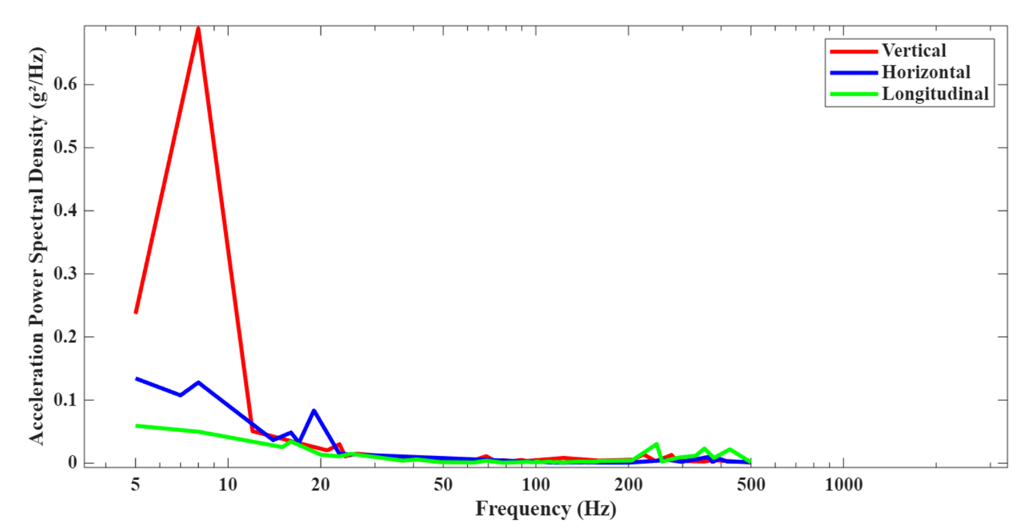
The transport input spectrum in all three axes, with the vertical
curve spiking sharply below 10 Hz and everything above 200 Hz running
close to the floor.
Figure 6 from: Jun Rao, Qiaoxin Zhang, Yu Feng, Meng Wei, Wentao
Yang. “Dynamic Characterization and Damping Enhancement
Mechanism of Carbon Fiber Reinforced Hybrid Structures for Aerospace
Electronics.” Polymers 2026, 18, 516.
https://doi.org/10.3390/polym18040516
— © 2026 by the authors. Licensed under CC BY 4.0.
The transport case uses the combined wheeled-vehicle profile from GJB150.16A, spanning 5 to 500 Hz across three axes. Assessment runs on root-mean-square von Mises stress.
Tables 3 & 4 — RMISES
Random vibration, judged at 3σ
ABAQUS reports RMISES as a 1σ statistic. The authors triple it and compare against yield.
Transport random vibration (GJB150.16A, 5–500 Hz)
Bump shock (GJB150.16A-2009, 0.001 g²/Hz, 1–100 Hz, z-axis)
Results as tabulated by Rao et al., Polymers 2026, 18, 516. RMISES is higher for the composite in every direction here; the authors' point is not that it is lower but that the tripled value still falls well short of the material's yield strength.
In both cases the authors report the tripled value falling well short of yield.
Sawtooth shock
The impact case follows GJB150.18A-2009. Each pulse peaks at no less than 40 g and lasts 11 ms, repeated three times down each of the six axis directions.
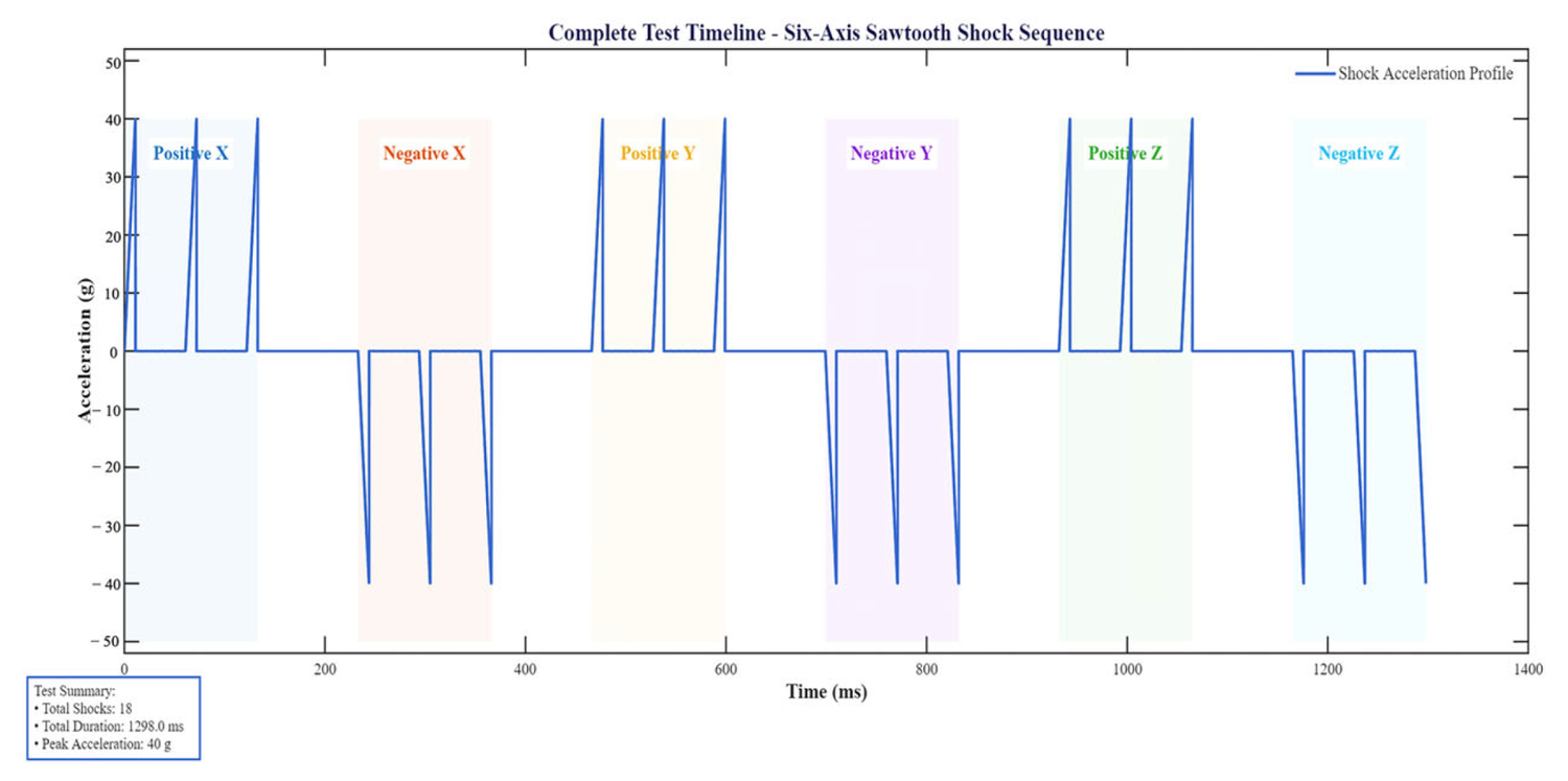
The full impact sequence: eighteen 40 g pulses, grouped into six
shaded blocks for ±x, ±y and ±z, inside 1298 ms
of test time.
Figure 9 from: Jun Rao, Qiaoxin Zhang, Yu Feng, Meng Wei, Wentao
Yang. “Dynamic Characterization and Damping Enhancement
Mechanism of Carbon Fiber Reinforced Hybrid Structures for Aerospace
Electronics.” Polymers 2026, 18, 516.
https://doi.org/10.3390/polym18040516
— © 2026 by the authors. Licensed under CC BY 4.0.
Table 5 — terminal peak sawtooth shock
A clean X-axis result, and a Z row we would not cite
Simulation results per axis. Tsai–Wu is a composite failure criterion; a value below 1 indicates no predicted failure.
Results as tabulated by Rao et al., Polymers 2026, 18, 516. We flag the Z row rather than reproduce it as fact: the 1356 MPa composite figure sits oddly against 81.3 and 98.4 MPa in the other two axes, and the Tsai–Wu index is printed on the aluminium row, where the criterion does not apply, while the composite's own entry is left blank.
The X-axis result is the striking one: 0.23 mm against 7.9 mm, with stress an order of magnitude apart. The authors summarise the table as showing lower deformation and lower stress for the composite throughout. That reading fits the X row cleanly. The Y row shows composite stress marginally above the metal, and the Z row carries a 1356 MPa figure for the composite that sits oddly against the 81.3 and 98.4 MPa values in the other two axes, and it prints a failure index on the aluminium row, where the criterion does not apply, while leaving the composite's own entry blank. We would restrict any citation of this table to the X-axis comparison unless the Z row can be clarified with the authors. Tsai–Wu indices land between roughly 0.075 and 0.086, an order of magnitude clear of the failure threshold.
On the shaker
Testing used an STI DC-10000-100 electrodynamic shaker, rated at 98 kN, capable of 51 mm peak displacement, 5 m/s, 50 g, across 1 to 2500 Hz. Only the vertical axis was tested. The reasoning: a tall console on a fixed base is softest in that direction and therefore absorbs the most energy from the input. The drive amplifier can take 9 V; the controller was deliberately capped at 5 V to protect the rig.
Control settings were conservative throughout. Analysis ran to 2000 Hz across 1600 lines at 1.25 Hz resolution, averaging over eight frames linearly and forty with weighting. Sigma-clipping was switched off and restart after an abort was disallowed, both choices that make the test harsher rather than easier.
Vertical-axis random vibration test
Stepped to full level, then an hour of it
Test procedure as described by Rao et al., Polymers 2026, 18, 516.
Sigma-clipping disabled and restart-after-abort disallowed, both of which make the test harsher rather than easier.
The console held level for the full hour. Nothing tripped an abort and no line exceeded its limit.
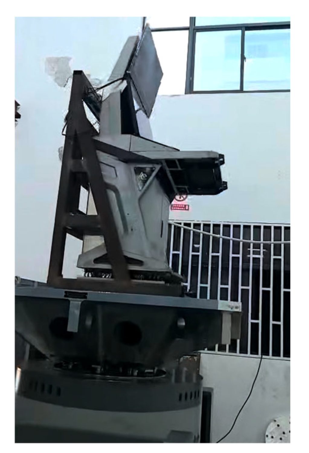
The finished console bolted to the shaker table through its fixture,
displays and payload fitted, ready for the vertical-axis run.
Figure 11 from: Jun Rao, Qiaoxin Zhang, Yu Feng, Meng Wei, Wentao
Yang. “Dynamic Characterization and Damping Enhancement
Mechanism of Carbon Fiber Reinforced Hybrid Structures for Aerospace
Electronics.” Polymers 2026, 18, 516.
https://doi.org/10.3390/polym18040516
— © 2026 by the authors. Licensed under CC BY 4.0.
Then they looked at the joints. When the console came off the table, inspection found the bolt holes securing the display bracket had gone slightly oval.
Nothing about the console's overall behaviour during the run had suggested a problem. The damage was entirely local, and it sat exactly where the model had the least resolution. Tying the bracket on through multi-point constraints had smeared that interface into something smoother and more forgiving than the real bolted joint.
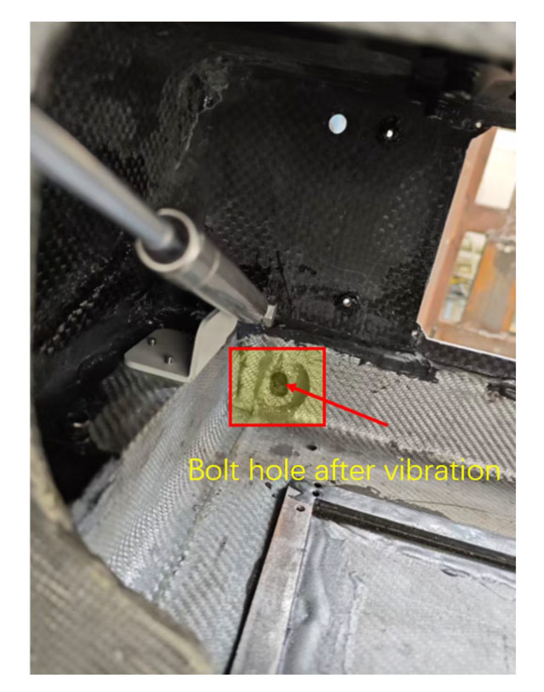
Post-test inspection inside the frame, with the elongated bolt hole
at the display bracket attachment highlighted where the metal meets
the laminate.
Figure 12 from: Jun Rao, Qiaoxin Zhang, Yu Feng, Meng Wei, Wentao
Yang. “Dynamic Characterization and Damping Enhancement
Mechanism of Carbon Fiber Reinforced Hybrid Structures for Aerospace
Electronics.” Polymers 2026, 18, 516.
https://doi.org/10.3390/polym18040516
— © 2026 by the authors. Licensed under CC BY 4.0.
The mechanism the authors set out is textbook bearing failure under reversing load:
Section 4.4 — the authors' discussion
How an aluminium bracket ovalises a hole in CFRP
Bearing failure at the metal–composite interface, under an hour of reversing random load.
An interference fit — squeezing the hole into compression before service, so vibration has to overcome that preload before it can open anything up.
Mechanism as set out by Rao et al., Polymers 2026, 18, 516, Section 4.4.
Water is the other problem, and the authors flag it as unresolved. It gets into the resin, softens it, drops the temperature at which the matrix turns rubbery, and works along the fibre interface. Stiffness across the fibres falls. The counterintuitive part is that a degraded interface dissipates more energy, so damping can rise towards saturation even as the fundamental frequency sags. They identify this as needing dedicated study for console structures and do not claim to have done it.
Our perspective: what this means for AFP work
Everything below is Addcomposites' commentary.
The console in this paper was laid up in prepreg and cured in an autoclave. Automated fibre placement was not used in this study. The authors have not evaluated AFP, our equipment or our software, and nothing in this section should be read as their endorsement of any of it.
With that said, four things follow.
The failure was a joint problem, not a laminate problem
The composite did what it was designed to do. Mass came down 40%, the fundamental moved off the high-energy part of the excitation spectrum, Tsai–Wu stayed low, the global response held for an hour. What moved was a hole. That pattern recurs across composite secondary structure: the panel passes and the attachment elongates. Local reinforcement at load introduction is not a refinement on hybrid assemblies, it is the design problem.
AFP changes the economics around those holes
A 25/25/50 stack at 5 mm is easy to write on a drawing and tedious to build consistently by hand across three separate mouldings. With AFP-XS, that schedule becomes programmed deposition with per-ply process data. More to the point, the same head laying the base laminate can add local doublers and steered reinforcement around insert positions in the same run. That turns local reinforcement from a labour cost into an engineering choice, which is a different conversation entirely.
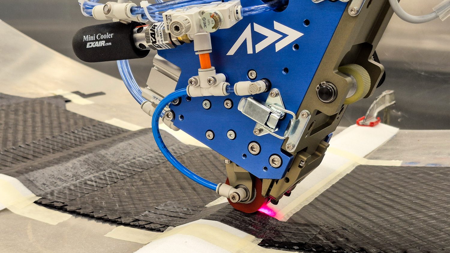
The Addcomposites AFP-XS head placing courses onto an in-progress laminate. Adding plies over a defined footprint is a change to the deposition programme, not a separate hand-layup operation — the staggered tow drops along the ply edge are where that footprint gets set.
Deterministic layup is what the damping model assumes
Because the loss factor is strain-energy weighted across parts and directions, small local deviations in fibre angle propagate into assembly-level damping. The model only predicts the part you actually built. AddPath exists so the ply strategy can be iterated, simulated and exported as a production programme, closing that gap.
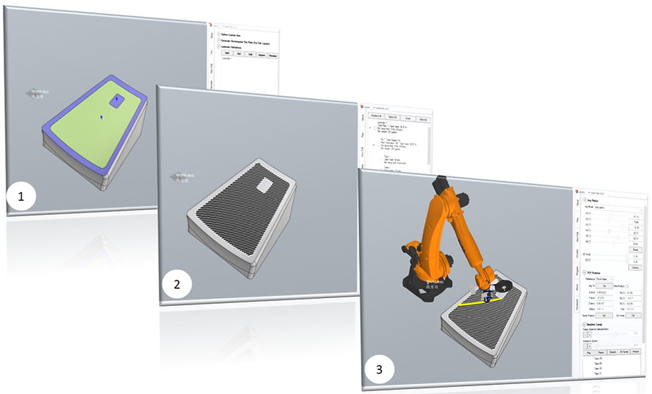
Three stages of the same job in AddPath: the surface and its boundary defined on the part, courses generated across it at the specified angle, then the whole run simulated with the head and robot before anything is deposited. The layup the damping model assumes is the layup the programme produces.
For eVTOL cabins this component class is underexplored
Our expectation, and it is an expectation rather than a citation, is that rotor and motor excitation in an eVTOL is more persistent and broader in band than fixed-wing, and that displays, avionics enclosures and interface panels sit inside it. The paper's console was tested in one axis on one article and says nothing about eVTOL, so nothing here is qualification. But a fundamental in the 130 Hz region is a useful reference point when scoping a console, and we would treat it as a starting hypothesis worth testing rather than a result to inherit. Where enclosure geometry is freeform and hard tooling does not pay at eVTOL volumes, ADDX takes a different route again: structural continuous-fibre 3D printing in PA, PEEK or PEKK, mould-free and programmed through AddPrint, which suits enclosure geometry that would never justify a hard tool. For cabin monuments beyond console scale, AFP-X covers the envelope.
Section 4.3 documents the bolt-hole elongation. The Conclusions state that no appreciable damage was observed. Those two passages do not agree. The Conclusions also describe the design as eliminating resonance risk, which sits awkwardly against the paper's own statement that the input spectrum carries a secondary band from 120 to 300 Hz, a band containing every one of the composite's first five modes. Point colleagues at Section 4.3 and the discussion after it, because that is where the transferable engineering sits.
Limitations
Two of the five authors are employed by Hubei Anxin Intelligent Technology, which also provided the test facilities; the paper declares this and states that it received no external funding. One console, one axis, one profile, one moisture state. The authors close by conceding that the constraints they modelled are cleaner than anything the console will meet in service, and they name hygrothermal behaviour as future work.
Things we would have liked to see and did not: a fatigue life estimate for the joints, a cost model, and any discussion of inspection or repair. None of that undermines the result. It means the result is a well-documented starting point rather than a qualified design.
Read the Research
- Rao, J.; Zhang, Q.; Feng, Y.; Wei, M.; Yang, W. “Dynamic Characterization and Damping Enhancement Mechanism of Carbon Fiber Reinforced Hybrid Structures for Aerospace Electronics.” Polymers 2026, 18, 516. doi.org/10.3390/polym18040516. Open access, published 19 February 2026 by MDPI under the Creative Commons Attribution (CC BY 4.0) license (creativecommons.org/licenses/by/4.0/).
- GJB 150.16A-2009 — Laboratory environmental test methods for military materiel, Part 16: Vibration test. Source of the combined wheeled-vehicle transport profile and the bump shock condition used in ref. 1.
- GJB 150.18A-2009 — Laboratory environmental test methods for military materiel, Part 18: Shock test. Source of the terminal peak sawtooth pulse (40 g, 11 ms, three per direction across six directions) used in ref. 1.
This article is an independent editorial summary and commentary produced by Addcomposites. It is not affiliated with, reviewed by, or endorsed by the study's authors or their institutions. All figures reproduced from ref. 1 under CC BY 4.0. Infographics are our own visualisations of data tabulated in ref. 1.
