CFRP Cryotanks Crack at Cryogenic Temperatures: A Resin Study That Targets the Root Cause
When carbon fibre-reinforced polymer (CFRP) replaces metal in a cryogenic tank, the carbon fibres are rarely the problem. The matrix is. At liquid-oxygen and liquid-hydrogen temperatures, conventional epoxy resins lose the small amount of molecular mobility that lets them tolerate strain, turn brittle, and crack between the fibres. Those matrix microcracks then link up into leak paths — the failure mode that has historically kept composite tanks out of the most demanding spaceflight roles.
A peer-reviewed, open-access study published in August 2025 in Polymers (MDPI) goes after exactly that root cause. A team from Zhejiang University's Institute of Advanced Equipment and Hydrogen Energy Institute set out to design an epoxy system that stays processable enough for wet filament winding and keeps usable toughness deep into cryogenic territory, then characterised both the neat resin and the resulting CFRP from room temperature down to 90 K.
The work is framed around onboard cryo-compressed hydrogen (CcH₂) storage vessels. But the underlying physics — matrix embrittlement, thermal-contraction mismatch, and the competition between cryogenic strengthening and thermal-stress damage — is the same physics that governs CFRP propellant tanks for launch vehicles and spacecraft. That overlap is what makes the paper worth a close read for anyone building cryogenic composite pressure structures.
A note on scope
Everything attributed below to "the paper," "the study," or "the authors" comes from Qi et al. Anything labelled Our perspective is Addcomposites' own analysis and does not represent a view, recommendation, or endorsement from the authors. Full citation and DOI are at the end.
Why the Matrix Is the Weak Link at Cryogenic Temperatures
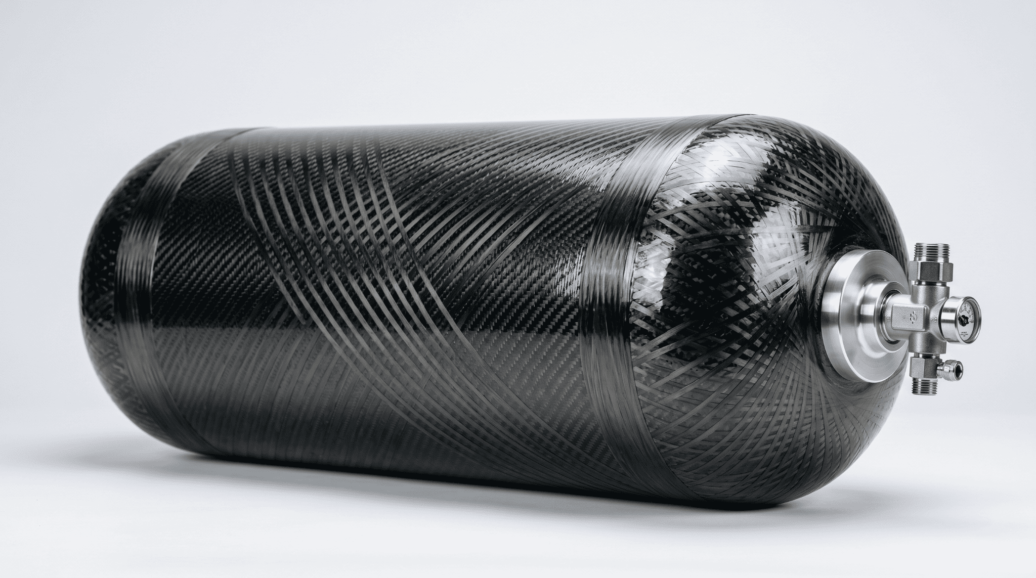
A filament-wound composite pressure vessel. The helical and hoop carbon fibre give the shell its strength; the matrix binding those fibres is what has to survive cryogenic thermal stress without cracking.
Decades of Evidence Point at the Matrix
The historical evidence for matrix-driven failure in composite cryotanks is hard to ignore. NASA's X-33 single-stage-to-orbit program saw its composite liquid-hydrogen tank fail in part because matrix microcracking opened permeation paths through the inner skin, as documented in NASA technical reporting from that investigation.
Later work through NASA's Composite Cryotank Technology Demonstration project showed that the problem is tractable — among other findings, that automated fibre placement (AFP) could fabricate large cryotanks at roughly 20–25% lower cost than baseline metallic approaches, and that thinner plies help resist the microcracks that drive hydrogen permeation. Reusability makes the stakes higher still: every fill-and-drain cycle reloads the structure with thermal stress born from the mismatch in contraction between fibre and matrix.
The mechanism is the same one the paper investigates. A vessel cured at elevated temperature and then cooled to cryogenic service experiences a large temperature drop. Because the resin contracts far more than the fibre, internal stress builds at the fibre–matrix boundary. The paper notes that for onboard vessels this cooling span can exceed 250 K, and that the resulting stresses can crack a brittle matrix — a risk that compounds when internal pressure is added on top.
Our perspective
The lesson across two decades of cryotank programs is that you do not solve a cryogenic matrix problem with laminate design alone. You solve it at the resin level, then verify it survives processing. That is precisely the order in which this study is structured, which is why it reads as a useful template rather than a one-off material result.
What the Study Actually Did
The authors started from a standard bisphenol-A epoxy (DGEBA, grade E51) and co-modified it with two additives chosen to balance flexibility against stiffness: a polyetheramine (Huntsman T5000) and a cycloaliphatic epoxy, CY179. The system was cured with methyl nadic anhydride (MNA) and accelerated with DMP-30. By weight, the formulation ran 80 parts E51, 20 parts T5000, 20 parts CY179, 93 parts MNA, and 1 part DMP-30 (parts per hundred resin).
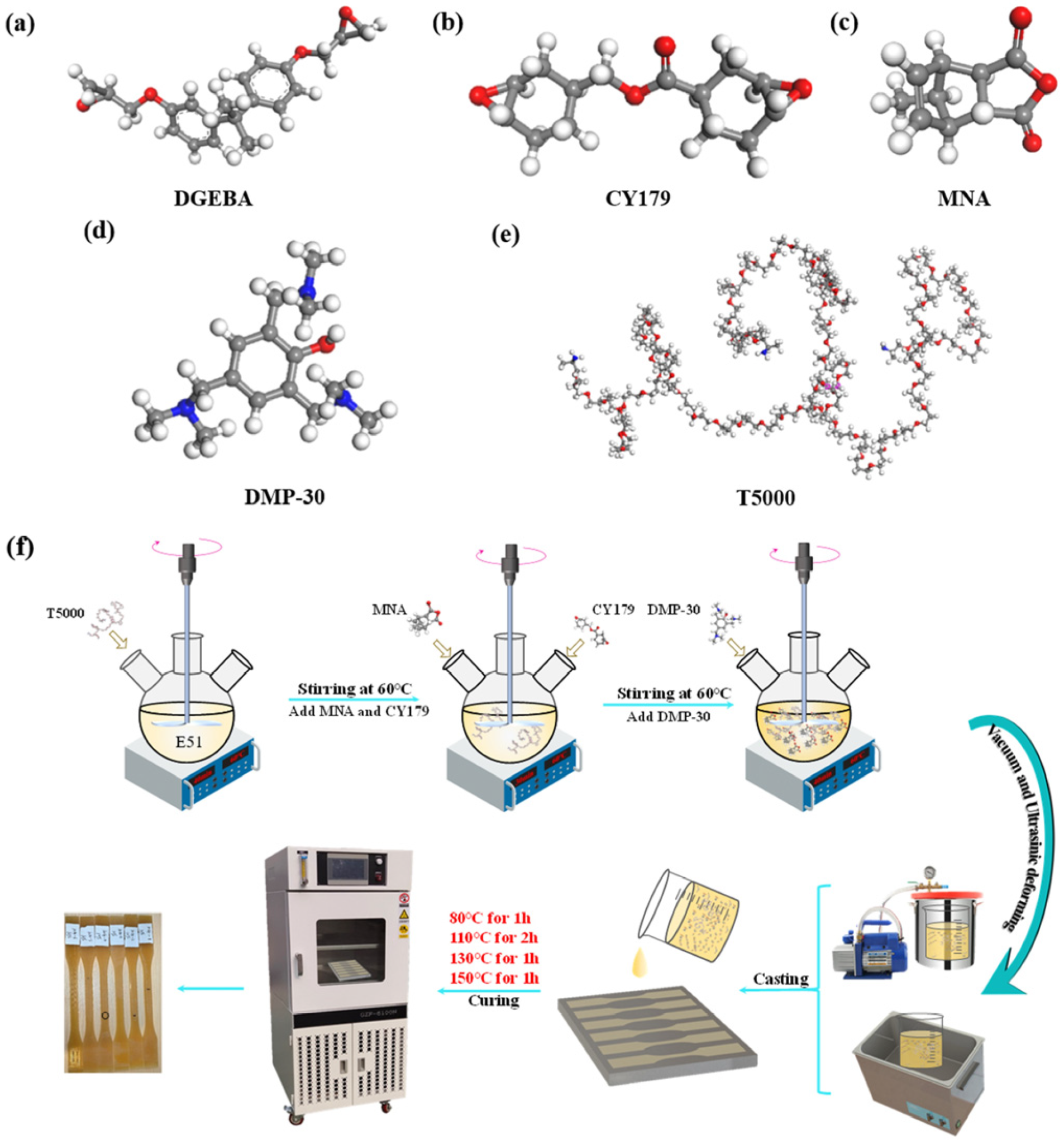
Ball-and-stick molecular models of the five resin components — DGEBA base epoxy, CY179 cycloaliphatic epoxy, MNA hardener, DMP-30 accelerator, and T5000 polyetheramine — alongside the step-by-step preparation flow of the modified epoxy, from mixing in a heated three-necked flask through the staged oven cure and casting. Figure 1 from: Qi, L.; Wang, K.; Ge, Z.; Cao, Z.; Hu, P.; He, Y.; Yasin, S.; Shi, J. "Investigation of Cryogenic Mechanical Performance of Epoxy Resin and Carbon Fibre-Reinforced Polymer Composites for Cryo-Compressed Hydrogen Storage Onboard Gas Vessels." Polymers 2025, 17, 2296. https://doi.org/10.3390/polym17172296 — © 2025 by the authors. Licensed under CC BY 4.0 (https://creativecommons.org/licenses/by/4.0/).
The intent behind the polyetheramine is structural. The paper describes it reacting with the epoxy as the system cures, growing branched, pliable chains that spread through the finished network — in effect seeding soft pockets inside an otherwise rigid thermoset, an interpenetrating-network approach meant to absorb energy and blunt cracks rather than let them run.
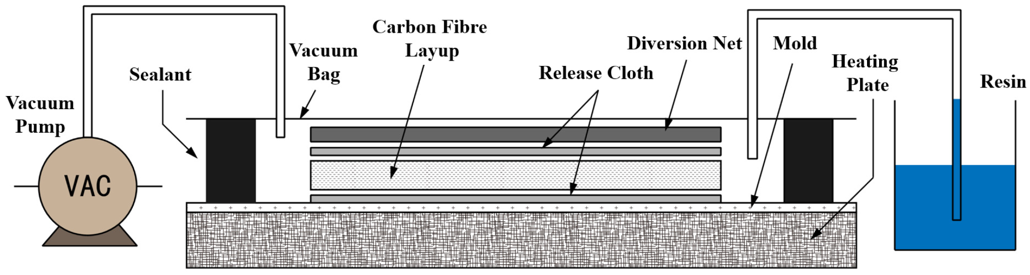
Cross-sectional schematic of the vacuum-assisted resin infusion (VARI) setup, showing the vacuum pump, sealant, vacuum bag, carbon fibre layup, release cloth, diversion net, and heated mold, with the resin reservoir feeding in from the side. Figure 2 from: Qi, L.; Wang, K.; Ge, Z.; Cao, Z.; Hu, P.; He, Y.; Yasin, S.; Shi, J. "Investigation of Cryogenic Mechanical Performance of Epoxy Resin and Carbon Fibre-Reinforced Polymer Composites for Cryo-Compressed Hydrogen Storage Onboard Gas Vessels." Polymers 2025, 17, 2296. https://doi.org/10.3390/polym17172296 — © 2025 by the authors. Licensed under CC BY 4.0 (https://creativecommons.org/licenses/by/4.0/).
From Resin to Composite Coupons
To make the composite specimens, the team used vacuum-assisted resin infusion (VARI) with T700 unidirectional carbon fibre, producing both longitudinal (0°, fibre-aligned) and transverse (90°, across-the-fibre) coupons. They then ran tensile tests and coefficient-of-thermal-expansion (CTE) measurements at five temperatures — 300 K, 250 K, 200 K, 150 K, and 90 K — and examined every fracture surface under SEM.
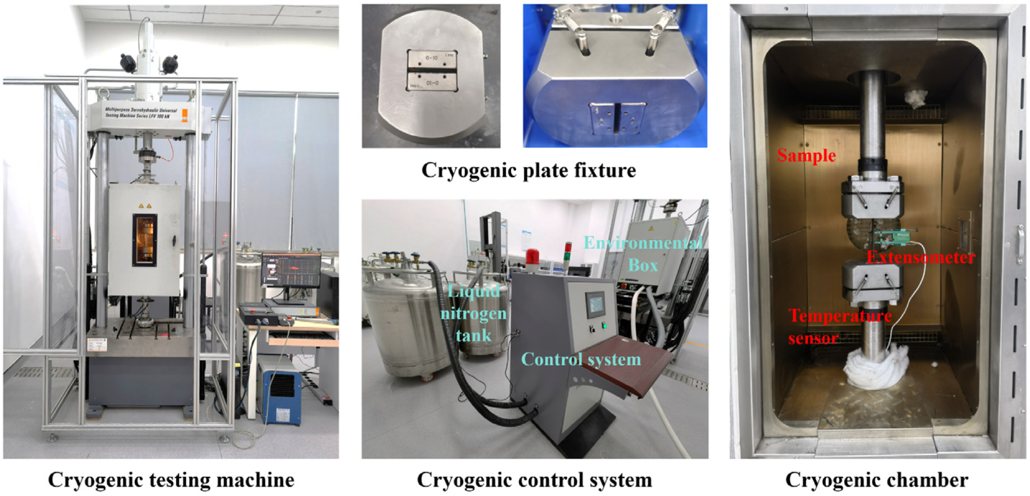
Photographs of the cryogenic tensile testing setup — the servo-hydraulic testing machine, the cryogenic plate fixture, the liquid-nitrogen control system, and the cooled chamber with the mounted specimen, extensometer, and temperature sensor. Figure 3 from: Qi, L.; Wang, K.; Ge, Z.; Cao, Z.; Hu, P.; He, Y.; Yasin, S.; Shi, J. "Investigation of Cryogenic Mechanical Performance of Epoxy Resin and Carbon Fibre-Reinforced Polymer Composites for Cryo-Compressed Hydrogen Storage Onboard Gas Vessels." Polymers 2025, 17, 2296. https://doi.org/10.3390/polym17172296 — © 2025 by the authors. Licensed under CC BY 4.0 (https://creativecommons.org/licenses/by/4.0/).
A point worth flagging for relevance: the authors measured a fibre volume fraction of roughly 41% in their VARI laminates and reported this closely matched the ~43.6% they measured in actual wet-filament-wound vessel specimens, which is their argument that the coupon data transfers to real wound hardware.
Processing First: The Viscosity Window That Makes It Windable
A resin that performs beautifully at 90 K is useless if it cannot impregnate fibre during layup. So the authors characterised flow before they characterised strength.
The paper reports the modified system at roughly 800 mPa·s at room temperature, sitting under the ≤850 mPa·s ceiling commonly specified for wet filament winding, and dropping to about 100 mPa·s near 60 °C — low enough for thorough fibre wet-out before the exotherm kicks in and viscosity climbs sharply toward gelation. The curing window itself, extrapolated from differential scanning calorimetry, runs from about 72.9 °C onset to 210.9 °C, which the authors describe as broad enough to allow flow before crosslinking locks the network.
Viscosity vs. Temperature
Modified DGEBA / T5000 / CY179 system · Qi et al., Polymers 2025
From the DSC and rheology, the authors built a four-stage cure — a pre-cure hold, two primary crosslinking stages, and a post-cure above the peak exotherm temperature — to drive the network toward full conversion while managing the thermal stress that develops during cool-down.
Our perspective
This is the detail that should catch a process engineer's eye. The headline result is cryogenic toughness, but the enabling result is that ~800 mPa·s number. A system that hits cryogenic targets yet behaves like honey at the tow is a lab curiosity; a system that wets out cleanly on a winding head is a manufacturing input. The paper treats processability as a gating requirement rather than an afterthought, and that ordering is the right one.
The Neat Resin: Stronger and Stiffer as It Gets Colder
Tested on its own, the modified resin did what a well-designed cryogenic thermoset should do — it got stronger and stiffer as temperature fell, with the trade-off showing up as reduced elongation.
The paper reports tensile strength rising from 69.2 MPa at 300 K to about 122.6 MPa at 90 K — roughly a 77% gain — while elastic modulus climbed from 2,433 MPa to 6,802 MPa, an increase near 180%. Both followed an essentially linear dependence on temperature, with the authors fitting strength and modulus against temperature at correlation coefficients around 0.98.
Neat Modified Resin — Tensile Properties vs. Temperature
DGEBA / T5000 / CY179 system · Qi et al., Polymers 2025, Table 3
What stops this from being a simple "colder is better" story is what happens to ductility. Above ~200 K the resin still yields and deforms noticeably; below 150 K, the authors attribute the change to the polymer running out of the internal room its chains need to move — so instead of yielding, it breaks. That is the embrittlement trap the modification is designed to soften.
And it does soften it, according to the fracture analysis. SEM of the resin's fracture surfaces showed dimples — a signature of plastic deformation — at every temperature tested, broad and open when warm and compressed into flatter, plate-shaped features when cold, but never gone entirely. The authors attribute this partly to phase separation: the polyetheramine does not disperse perfectly, leaving a "soft phase / hard phase" morphology. Small soft domains act as pinning points that catch and redirect advancing cracks, and the surfaces show the resulting toughening behaviour — cracks that change direction, particles tearing loose from the matrix, and debonding at the fibre–resin interface. The authors are careful to note the limit of this: too high a density of phase-separated regions creates stress concentrations that can seed cracks instead of stopping them.
The Thermal-Mismatch Problem, Quantified
Before the composite results make sense, the CTE story has to be on the table — because the thermal mismatch between fibre and matrix is the source of the internal stress that drives cryogenic cracking.
The paper reports the carbon fibre as nearly thermally inert along its axis (axial CTE around −0.9 × 10⁻⁶/K) and modestly expansive across it (transverse CTE about 7.2 × 10⁻⁶/K). The resin, by contrast, moves on cooling by something close to ten times that amount. That gap is exactly why a wound or laid-up laminate develops residual stress on cooling: two bonded materials want to shrink by very different amounts.
CTE Comparison — Why the Matrix Drives Thermal Stress
Representative values · Qi et al., Polymers 2025, Tables 2 & 6
In the fibre direction, the composite's contraction is governed by the near-inert fibres, so the longitudinal CTE stayed low and barely changed with temperature. Across the fibres, the matrix dominates, so the transverse CTE was much higher — and it decreased as the resin stiffened on cooling. This asymmetry is the seed of the most important composite-level finding.
The Headline: 0° Barely Moves, 90° Transforms
When the authors tested the actual CFRP, the two fibre orientations behaved like almost different materials — and that contrast is the practical core of the paper.
Longitudinal (0°, load along the fibres). Properties were dominated by the carbon fibre, which the authors note is only minimally temperature-sensitive. From 300 K to 90 K, tensile strength rose only about 4.3% (1,928.9 → 2,010.4 MPa) and modulus about 7.7%, with elongation down slightly. Stable, predictable, fibre-controlled.
Transverse (90°, load across the fibres). Here the matrix and the interface carry the load, so the resin's cryogenic strengthening showed up directly. The paper reports transverse tensile strength up about 52.2% (43.1 → 65.6 MPa) and transverse modulus up about 82.4% (6,561 → 11,969 MPa) over the same span.
Property Gain: 300 K → 90 K
CFRP laminate orientations · Qi et al., Polymers 2025, Tables 7 & 9
There is a subtlety in the longitudinal modulus that the simple percentage hides. Rather than rising monotonically, it climbed to a peak near 150 K and then dipped slightly. The paper reports it going from 95.8 GPa at 300 K up to 104.8 GPa at 150 K, then back down to 103.3 GPa at 90 K.
CFRP-0° Longitudinal Modulus — Peak near 150 K
Qi et al., Polymers 2025, Table 7 / Figure 12b
The Two Competing Mechanisms
The authors explain all of this through a tug-of-war between two effects that both intensify as temperature drops.
Mechanism 1 — cryogenic strengthening. Resin and fibre both stiffen, and matrix contraction tightens the grip on the fibres ("encapsulation"), so the bond carries load better between the two. This pushes strength and modulus up.
Mechanism 2 — thermal-stress microdamage. The same contraction mismatch that improves encapsulation also builds internal stress, which can debond the interface and crack the matrix. This pulls properties down.
Which Mechanism Wins?
Competing effects at low temperature — outcome depends on what carries the load
- Stiffer resin matrix
- Tighter interfacial bonding
- More efficient load transfer
- Thermal-stress microcracking
- Interfacial debonding
- Accumulated damage on cooling
The fracture surfaces backed this up. In the 0° coupons, the authors saw failure driven by the fibres themselves snapping, with resin clinging to and linking the fibres. The 90° surfaces showed a mix of matrix cracking and interfacial debonding, with shear bands forming because resin trapped between fibres is too constrained to deform in simple tension. The telling detail: at colder temperatures, the broken surfaces carried more clinging resin and a coarser texture — evidence that the bond was getting stronger, not weaker, in the transverse direction, even as the count of microcracks climbed alongside it. That coexistence is the whole point: toughening does not eliminate thermal-stress damage; it tips the balance so strengthening wins.
Why This Matters for AFP and Filament-Wound Cryogenic Structures
Our perspective
The finding that lands hardest for a manufacturer is the orientation split. In a real wound vessel or tank, hoop and helical plies put the matrix and interface in the load path — the conditions that map onto the 90° coupon, where this resin showed its biggest gains. The directions most vulnerable to cryogenic matrix cracking are exactly the directions where the modification did the most work. For anyone designing winding patterns or AFP layups for cryogenic service, that is an argument for treating the resin system as a first-class design variable, not a fixed input.
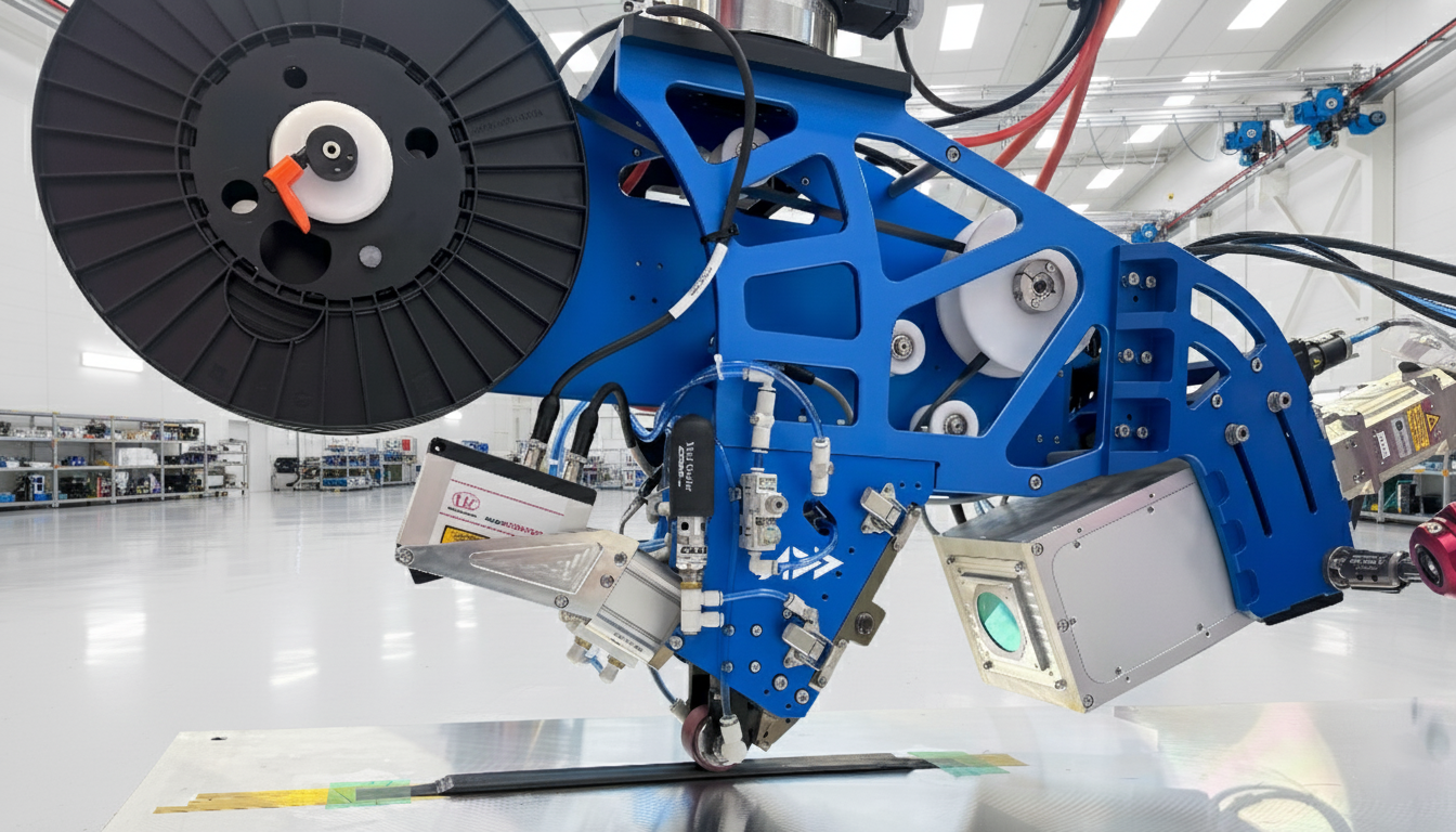
The Addcomposites AFP head placing a carbon fibre course during automated fibre placement. The same head also runs filament winding — switching between them is set in software, not new hardware.
One Cell, AFP and Filament Winding
It also reinforces a position we hold about process choice. The Addcomposites AFP head is configurable for both automated fibre placement and filament winding — switching between them is a software and materials decision in AddPath (toolpath planning and simulation) and AddWind (filament winding simulation), not a separate capital purchase. A resin characterised here for wet filament winding, at a viscosity our customers' processes can handle, sits naturally inside that flexibility. The same cell that lays AFP courses onto a mandrel can wind hoop and helical layers with a wet system in this viscosity class.
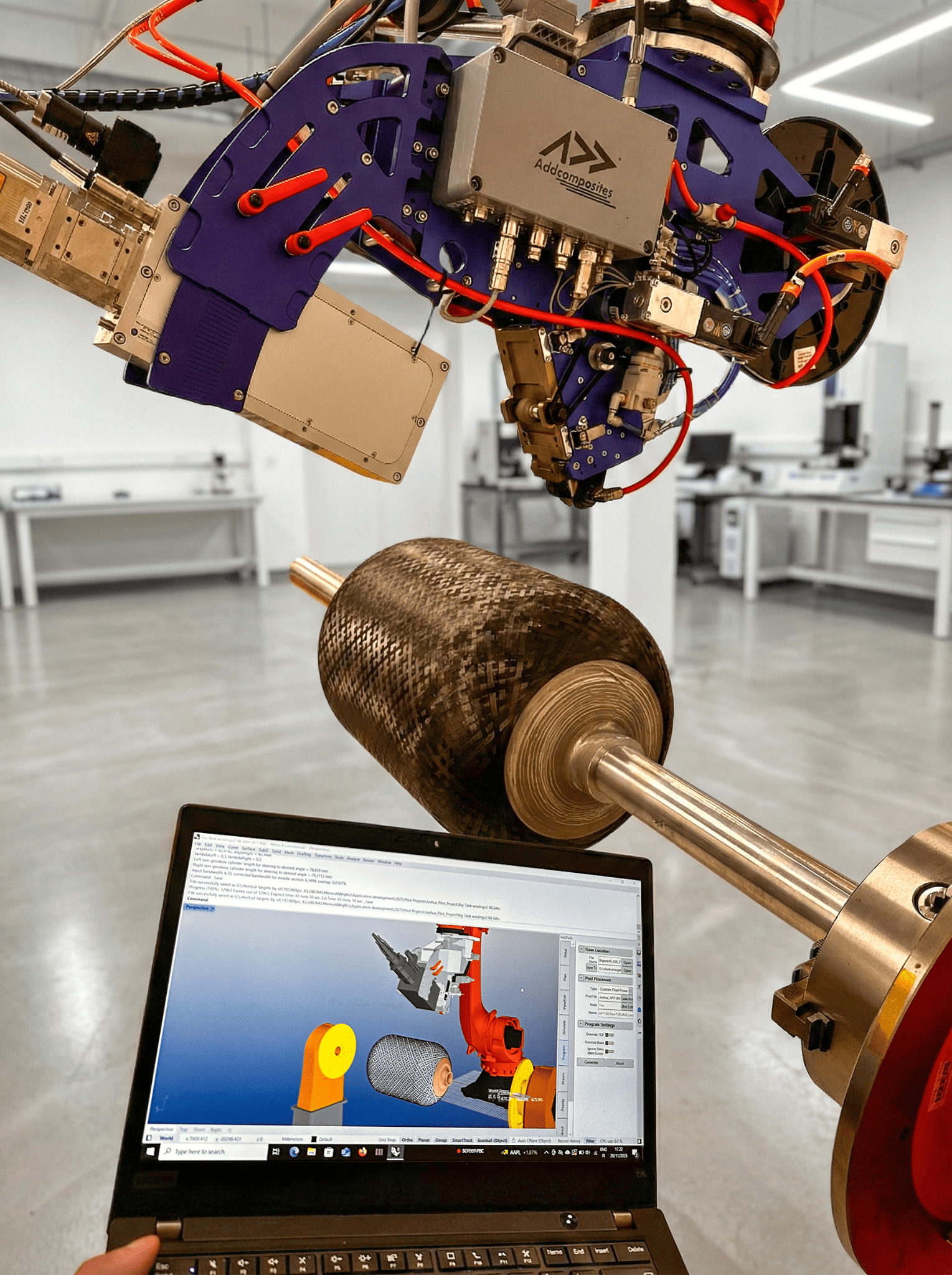
The cell winds hoop and helical carbon fibre onto a mandrel while the same layup is planned and simulated in AddPath on the laptop. The choice between AFP and filament winding is made here, in software — not with new hardware. The same head winding hoop and helical carbon fibre layers onto a mandrel. A wet resin in the viscosity class characterised in this paper fits naturally into this process.
A few honest boundaries, because the marketing angle should not outrun the data:
- The paper is about hydrogen storage vessels, not propellant tanks. The physics transfers cleanly — matrix embrittlement and CTE mismatch behave the same way regardless of what is inside the tank — but the authors did not test propellant-tank hardware, and nothing here should be read as their endorsement of any spaceflight application.
- The tested floor is 90 K. That is close to liquid-oxygen service (~90 K). Liquid hydrogen sits near 20 K, below the range these tests cover. Extending the trends to 20 K is extrapolation on our part, not a measured result, and matrix behaviour can change in ways linear fits will not predict.
- This is a wet-infusion / wound system. The authors fabricated coupons by VARI and validated against wound vessels. We are not claiming the paper proves out a prepreg AFP process; the relevance runs through the wet filament winding pathway and the shared physics.
Our perspective on the bigger picture
The value of work like this to an AFP or filament-winding operation is that it narrows the materials search. When a customer asks whether composite can replace metal in a cryogenic tank, the honest historical answer has been "the fibres can, but the matrix is a liability." Studies that quantify a processable resin's cryogenic behaviour — and explain why it behaves that way, mechanism by mechanism — are how that liability gets retired. Pairing a characterised resin system with deterministic toolpath and winding simulation is how a promising chemistry becomes a repeatable, qualifiable part.
What the Authors Flagged as Next Steps
The paper closes by pointing forward, not declaring the problem solved. The authors flag two open questions: how the balance of resin to fibre shapes the interface and the way the laminate expands and behaves in the cold, and — importantly for reusable hardware — how the material holds up across repeated cold cycles rather than a single cool-down. That last point matters: as the broader cryotank literature shows, it is repeated fill-and-drain cycling, not a single cold soak, that historically accumulates the microcrack networks responsible for leakage.
Learn More
Get in touch to discuss your cryogenic composite application →
Contact Us for a ConsultationRead the Research
This article summarises and comments on the following open-access paper. For the full methodology, figures, and data, read the original:
- Qi, L.; Wang, K.; Ge, Z.; Cao, Z.; Hu, P.; He, Y.; Yasin, S.; Shi, J. "Investigation of Cryogenic Mechanical Performance of Epoxy Resin and Carbon Fibre-Reinforced Polymer Composites for Cryo-Compressed Hydrogen Storage Onboard Gas Vessels." Polymers 2025, 17, 2296. https://doi.org/10.3390/polym17172296
© 2025 by the authors. Published by MDPI, Basel, Switzerland. This is an open-access article distributed under the terms of the Creative Commons Attribution (CC BY 4.0) license (https://creativecommons.org/licenses/by/4.0/).
Addcomposites is not affiliated with the authors or their institutions. References to NASA programs and other cryotank literature are drawn from publicly available technical reporting and are used here for context only.